
- Catalogs
- MITSUBISHI Automation
- Data CC-Link/LT Safety


Data CC-Link/LT Safety

Data CC-Link/LT Safety
- Input Specifications: The modules support 8 to 32 input points with photocoupler isolation, rated for 24VDC. The operating voltage range is 19.2 to 26.4VDC, with a maximum input current of approximately 5mA. The response time is 0.2ms to 1.5ms depending on the module.
- Output Specifications: Output modules support 8 to 32 points, with a rated load voltage of 12/24VDC. The maximum load current is 0.1A per point, with protection functions against overload, overvoltage, and overheating.
- Noise Immunity and Protection: The modules are designed to withstand 500Vp-p noise and 500VAC for 1 minute between all DC external terminals and ground. They have an insulation resistance of 10MΩ or higher.
- Environmental and Physical Characteristics: The protection level is IP1XB or IP2X, and the weight ranges from 0.15kg to 0.19kg depending on the module.
- PW: Indicates power status.
- L RUN: Indicates normal data reception from the master station.
- L ERR: Indicates transmission errors.
- X0 to 1F, Y0 to 1F: Show input/output status.
- Transmission Speed: Configurable between 156kbps, 625kbps, 2.5Mbps, 5Mbps, and 10Mbps.
- Terminating Resistor: 110Ω is required for both trunk and branch lines. The use of 130Ω is not allowed for AJ65FBTA-RPH.
- Power Supply: 24VDC external power supply with a ripple within ±5%.
- Mounting: Modules can be mounted in six orientations using M4 screws.
- Connect the 110Ω terminating resistor at the end of each segment.
- Ensure the transmission speed of each segment matches the master station.
- Connect the shielding wire of the CC-Link dedicated cable to "SLD" and ground via "FG".
- For AJ65BTS-RPH, use the built-in 110Ω terminating resistor for branch lines.
- Star-topology wiring with up to 8 branch lines is supported.
- Spring clamp terminal blocks reduce maintenance costs and improve ease of installation.
- Modules allow for system separation to quickly identify errors without affecting the entire system.
- Maximum number of modules connected to the trunk line is 64.
- Maximum number of stages per segment is two.
- Modules are compliant with CC-Link specifications for trunk line connections.
- Ensure consistent use of CC-Link dedicated cables within each segment to maintain data transmission integrity.
- Refer to the user manual for specific details on terminating resistor types based on cable type.
The document outlines the specifications for a remote I/O module system. Key specifications include:
- Input: 8 points with photocoupler isolation, 24VDC rated input voltage, and a response time of 0.4ms or lower.
- Output: 4 points with photocoupler isolation, 24VDC rated load voltage, and a maximum load current of 0.5A per point.
- Noise immunity: DC type noise voltage 500Vp-p, noise width 1µs, noise frequency 25 to 60Hz.
- Protection level: IP2X with a weight of 0.67kg.
The document provides detailed wiring methods and connection diagrams for setting up the modules. It emphasizes the use of dedicated flat cables and connectors for efficient system configuration.
Recommendations include using identical terminating resistors at both ends of the trunk line and placing them close to the master module. The document also suggests using cables approved by the CC-Link Partner Association.
Examples of system configurations using different point modes (4-point, 8-point, 16-point) are provided. These examples illustrate how to efficiently manage I/O points and station occupancy.
The document includes diagrams for external device connections, terminal layouts, and system configurations. Tables provide detailed specifications for input and output modules, including voltage, current, and response times.
- Input Module Specifications: The input modules are available in different configurations (e.g., CL2X8-D1S2, CL1X4-D1S2) with 8 points/common and a voltage range of 20.4 to 28.8VDC. The response speed can be set to 0.5ms for high-speed or 1.5ms for standard speed using DIP switches.
- Output Module Specifications: Output modules (e.g., CL2Y8-TP1S2, CL1Y4-T1S2) feature a rated load voltage of 12/24VDC and a maximum load current of 0.1A per point. The HOLD function can be set to either CLEAR or HOLD.
- DIP Switch Settings: Used for setting response speed and station numbers. All DIP switches are set to OFF prior to shipment.
- LED Indicators: LEDs indicate power supply status, communication status, and errors.
- Model: CL2AD4-B
- Input Range: Voltage (-10 to 10V, 0 to 10V, 0 to 5V, 1 to 5V), Current (0 to 20mA, 4 to 20mA)
- Resolution and Accuracy: Maximum resolution of 15-bit signed binary, with accuracy varying by input type (e.g., ±0.4% for voltage inputs)
- Conversion Speed: 200µs for 4 channels
- Isolation: Photocoupler and transformer isolation between systems, no insulation between channels
- Installation: DIN rail installation, compatible with specific terminal blocks and wire sizes
- Power Supply: 24VDC with specific current consumption requirements
- Model: CL2DA2-B
- Output Range: Voltage (-10 to 10V, 0 to 10V, 0 to 5V, 1 to 5V), Current (0 to 20mA, 4 to 20mA)
- Resolution and Accuracy: Similar to input module, with specific accuracy for each output type
- Conversion Speed: 200µs for 2 channels
- Isolation: Similar isolation specifications as the input module
- Installation: Similar DIN rail installation requirements
- Power Supply: 24VDC with specific current consumption requirements
- Models: CL1PAD1 (Power supply adapter), CL1PSU-2A (Power supply)
- Specifications: Detailed voltage, current, and insulation specifications provided
- Installation: Guidelines for selecting and installing power supplies, including current consumption and voltage drop calculations
- Terminal Blocks: Specifications for connectable terminal blocks and applicable wire sizes
- External Connections: Diagrams and descriptions for connecting external devices
- Temperature coefficients and ambient temperature ranges are specified for both input and output modules.
- Detailed diagrams and layouts are provided for module installation and external connections.
- High-precision operation robots with a maximum load capacity ranging from 5kg to 15kg and arm lengths between 350mm to 850mm. These are oil mist proof and suitable for clean-room environments with a cycle time of 0.46 seconds.
- High-speed palletizing robots designed for material handling with a maximum load capacity of 100kg to 150kg and arm lengths from 2360mm to 2730mm, capable of processing up to 1600 cycles per hour.
- Large glass substrate transfer robots with various axis structures available, suitable for different substrate sizes and layouts, featuring a deflection correction function for high-speed and high-precision transfers.
- MDU Breaker: Features a display function for measuring load current, line voltage, electric power, and more, supporting energy-saving activities. It is space-saving with built-in VT and CT, suitable for various applications with a wide range of rated currents.
- Energy Measurement Modules: Various models (EMU2-HM1-C, EMU2-RD1-C, etc.) are available for measuring multiple circuits, supporting both low and high-voltage applications, and compatible with CC-Link communication.
- Eco Monitor II: Measures current, voltage, electric power, and energy values of multiple low-voltage circuits simultaneously. It supports data collection and management via networks for energy-saving systems.
- MELPRO-D Series: Advanced communication network-compatible relays for automatic power distribution, suitable for high-voltage systems protection with various measurement functions and programmable contacts.
- Specifications for CC-Link Version 1.10 include transmission speeds, maximum cable lengths, and connection guidelines. It supports various network configurations and error control systems.
- Input modules are available in configurations of 4, 8, 16, and 32 points with voltage options of 5VDC and 24VDC.
- Response times vary from 0.2ms to 10ms, with options for high-speed response.
- Common types include positive/negative common shared and positive common configurations.
- Output modules are available in configurations of 4, 8, 16, and 32 points with voltage options of 12/24VDC and 24VDC/240VAC.
- Output types include transistor (sink/source type), relay, and triac outputs.
- Current ratings range from 0.1A to 2A, with low-leakage current options available.
- Various models such as AJ61BT11, A1SJ61BT11, and QJ61BT11N are listed, indicating compatibility with different module types and configurations.
- Includes safety relay modules, analog modules, high-speed counter modules, and positioning modules.
- Peripheral connection modules and RS-232 interface modules are also available.
- Details on CC-Link Safety inputs and outputs, A/D and D/A conversion modules, and temperature input modules.
- Information on communication LSI for lead-free/RoHS compatible stations.
- One-touch connector plugs, protective covers, and dustproof/waterproof caps are specified for various applications.
- 40-pin connectors and module mounting brackets are also detailed.
- Protection levels range from IP1X to IP67, indicating varying degrees of protection against dust and water ingress.
The document outlines specifications for various Mitsubishi Electric products, including one-touch connector plugs for communication and power supply, applicable cable types, and wire sizes. It specifies the maximum number of stations (64, with 42 safety stations) and details safety input and output points.
It lists model names for CC-Link Safety and CC-Link/LT related products, including master modules, remote I/O modules, and accessories like connectors and cables. The document also mentions protection levels (IP2X) for different module types.
The document advises reading manuals before using the products and highlights that these products are designed for general industrial use, not for critical applications like nuclear or aerospace without consultation. It emphasizes the importance of backup or failsafe functions in systems where product failure could cause significant damage.
Users are cautioned to check detailed specifications and restrictions in the Q series data book and to read user manuals. Mitsubishi disclaims liability for damages not caused by their products or for secondary damages.
The document provides contact details for Mitsubishi Electric offices worldwide, including in the USA, Brazil, Germany, UK, Italy, Spain, France, South Africa, Hong Kong, China, Taiwan, Korea, Singapore, Thailand, Indonesia, India, and Australia.
Catalog excerpts

Open Field Network CC-Link Compatible Product databook IndUStrieS Platform Mitsubishi Electric Corporation Nagoya Works is a factory certified for ISO14001 (standards for environmental management systems) and ISO9001 (standards for quality assurance management systems) BUREAU VERITAS
Open the catalog to page 1
Strategic Network CC-Link Safety. Strong Manufacturers Stay One Step Ahead of Oth el CC-Link Safety Let's Start Powerful Factory Automation Let's Connect with Powerful Networks. System Configuration Example 25 <CC-Link Safety> System Configuration Example 161 System Configuration
Open the catalog to page 2
Opening up the Future of FA Networks and Focusing on what's to come. Changes for the better - Mitsubishi Electric We provide total support in constructing seamless networks in all scenes, from offices to production sites, under a consistent design philosophy. With flexible approaches backed by "Ethernet," "MELSECNET/H" and "CC-Link", a SEMI-certified, world standard field network originated in Japan, and "CC-Link/LT", a sensor level network adhering to the design concept of CC-Link, we propose a network-based FA environment, fit for your needs. the network over all layers <Between factory departments:...
Open the catalog to page 3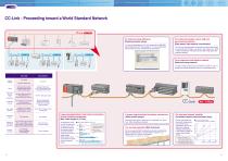
CC-Link - Proceeding toward a World Standard Network For improved setup efficiency [Simple parameter setup] For achieving complex control, high-mix low-volume production [High-speed, high-capacity transmission] You can set parameters on CC-Link using only the MELSEC total programming tool "GX Developer." You can significantly reduce program size and efficiently set parameters. For a simple and cost effective network [Reduced-wiring network] CC-Link is a high-performance network that utilizes high-speed communications (10 Mbps -top level in the industry-), in order to allow transmission of bit...
Open the catalog to page 4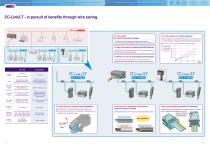
CC-Link/LT - in pursuit of benefits through wire saving. For Easy usage [No need of parameter settings] For high-speed control [fast response] Troublesome network parameter setting is unnecessary. The communication speed setting is required for the master module only. When 64 stations are connected, link scan time is a maximum of 1.2 ms(at 2.5Mbps), achieving excellent fast response performance. CC-Link/LT Link Scan Time (at communication speed of 2.5 Mbps) For Efficient use of I/O points [No wasting surplus I/O points] CC-Link/LT also inherits the feature of CC-Link, complies with EMC directives...
Open the catalog to page 5
Innovation in shop floor safety, CC-Link Safety A safety field network "CC-Link Safety" has been developed to reduce risks on the shop floor and to realize a safe work environment. By connecting "safety devices," which detect errors in the production line, and the "safety programmable controller," which stops the production line by signals from the safety devices, with simple wiring, accidents can be prevented during operation. In addition, CC-Link Safety can greatly reduce wiring for the safety system. Risk sources of production lines Mechanical risk Noise/vibration risk Electrical risk Enclosing...
Open the catalog to page 6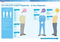
For hose in design, production and maintenance CC-Link & CC-Link/LT provide solutions for each challenge in the field. More functions... CC-Link "I want a flexible production system." "I want to arrange devices as I desire." "I need complex control features." "I need assembly/ disassembly to be easy." Preventing trouble CC-Link CC-Link/LT "I need network testing for preventive maintenance." CC-Link "I want to do network maintenance from sites away from the PLC master." "I want to connect lots of analog devices." Maintenance section "I need high noise resistance." At testing/operation... CC-Link...
Open the catalog to page 7
CC-Link ensures... CC-Link is a high-speed and high-capacity network. CC-Link guarantee consistent communication time. CC-Link is a high speed field network that can handle both control and information together. The cyclic transmission time is not affected by irregular message transmission to the HMI products. It is possible to achieve highly stable control. CC-Link Link Scan Time (at communication speed of 10 Mbps) High-speed/High-capacity data transmission MODE RUN ERR USER BAT BOOT Data capacity Remote I/O (RX, RY)=8192 points each Remote register (RWw)= 2048 words (RWr)=2048 words (when Ver2.0...
Open the catalog to page 8
I want to arrange devices as I desire. CC-Link allows flexible installation. I need assembly/ disassembly to be easy. CC-Link family remote I/O modules occupy a small footprint. T-branch repeaters, wireless optical repeaters, optical repeaters, and repeater hubs are available with CC-Link. They enhance the freedom of application even at 10 Mbps. Repeater hub Compact type remote I/O modules with 32, 16, 8, 4, and 2 I/O points are available. They can be mounted in six different directions, including ceiling mounting, front mounting, and flat surface mounting, and selected according to the environment...
Open the catalog to page 9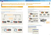
Requests from the maintenance section: "Don't want to stop CC-Link & CC-Link/LT supports the maintenance work with system and keep high operating rates!!" secure functions. Before trouble occurs... (preventive maintenance) When trouble occurs... (troubleshooting) "I need network testing for preventive maintenance." "I don't want to stop my system." CC-Link provides enhanced RAS functions. Station is made offline when a station error occurs, and the data link is continued on normal operating stations. There is no need to move the PC to where the PLC CPU is installed. MODE RUN ERR USER BAT BOOT...
Open the catalog to page 10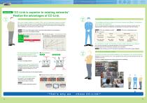
Case Study "CC-Link is superior to existing networks" Realize the advantages of CC-Link. CASE Mr. A from the engineering section "My current network distance is limited to 100m, and the transmission speed is unstable." "Trunk cables and branch cables in the current network are different. Furthermore, trunk cables are expensive." Mr. A plans to expand his factory. The first challenge is total cable distance and communication stability. What interested him is that the network distance covered by the CC-Link network can be increased up to 900m at 625kbps, and transmission time is stable as well....
Open the catalog to page 11All MITSUBISHI Automation catalogs and technical brochures
 MELSEC iQ-R Series
120 Pages
 MR-FAMILY
117 Pages
 FR-A741
4 Pages

Archived catalogs
 MR-J4
MR-J44 Pages
 the automation book
188 Pages
 Q/L-Family MELSEC Modular PLC
114 Pages
 MELSEC System Q
84 Pages
 MR-J3-BSafety
4 Pages
 FX3UC
FX3UC4 Pages
 HMI E1000
4 Pages
 ST series
4 Pages
 SPAC
SPAC2 Pages
 Material Handling
28 Pages
 SUPER AE-SW
4 Pages
 203684
52 Pages
 Data 2009
8 Pages
 Data Redundant System Q Series
27 Pages
 219952
28 Pages
 LVS Family
116 Pages
 MR Family
90 Pages
 HMI Family
58 Pages
 MELSEC STlite
4 Pages
 L series
4 Pages
 FX Family
90 Pages
 Micro controller ALPHA 2
4 Pages
 Mitsubishi Magasine
20 Pages
 Automotive
20 Pages
 MELSEC Process Control Catalog
13 Pages
 MELSEC iQ-R series/System Q/L series
166 Pages


- Mitsubishi Electric electric motor
- Panel PC
- Industrial panel PC
- Panel PC with touch screen
- Industrial robot
- Fanless panel PC
- Mitsubishi Electric AC motor
- LCD panel PC
- Mitsubishi Electric automation software
- Management software solution
- Intel® Core™ PC
- Industrial computer
- Fanless PC
- Intel® Core™ panel PC
- Box PC
- Analysis software solution
- Windows PC
- Electromotor for industrial applications
- Process software
- Windows 10 panel PC