Group: AMETEK

Catalog excerpts

TUFFY® T3 Side Mounting Level Controls Tuffy liquid level switches are float actuated devices designed for horizontal mounting in a tank or vessel through threaded or flanged pipe connections. The compact size allows for installation in small vessels, while its many features provide a variety of application uses. The single switch mechanism is available in SPDT or DPDT forms on units designed for adjustable, narrow or wide differential and interface service. Compact and cost effective Maximum Process temperature: +400 °C (750 °F). Minimum Process temperature: -55 °C (-65 °F). Maximum process Pressure: 150 bar abs (2160 psi). Specific gravities as low as 0.4. Wetted parts in 316/316L (1.4401/1.4404) or Hastelloy C (2.4819). Available as: - Flanged - Threaded - Flanged or sealed cage mounted. External cage mounted Tuffy Shut-off valve Narrow differential switch (for alarm functions) - standard pressure (up to 50 bar abs (720 psi) - high pressure (up to 150 bar (2160 psi). Wide adjustable differential switch (for control functions) Interface switch (detection of interface level between liquids). External cages. Compact versions: - pneumatic narrow differential switch - electric narrow differential switch. Safety check valve Sour service (NACE). High/low alarm. Single pump control. Day storage tanks. Corrosive processes. Process vessels. Boiler low water cut off. Interface level. Dirty process high level w/offset. Installations in hazardous area. Shut-off valve Switch actuation level Drain valve Pressure vessel Typical piping arrangement AGENCY APPROVALS Agency ATEX (zone 0) FM/CSAx II 1/2G EEx d II C T6, explosion proof II 1G EEx ia II C T6, intrinsically safe Explosion proof x Consult factory for proper partnumbers
Open the catalog to page 1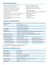
SWITCH MECHANISMS All TUFFY® are available with a selection of switch modules that vary in switch rating (Amp) and max process temperature allowance. The max temperature is dependent upon the housing material selected. Consult table below, before selecting the proper module in the order number structure on pages 3, 5, 7 or 9. Electric switch rating V AC V DC Contacts and type 120 240 24 120 SPDT with silver contacts 10.0 10.0 6.0 0.6 DPDT with silver contacts 10.0 10.0 6.0 0.6 SPDT with gold plated contacts 0.1 0.1 DPDT with gold plated contacts 0.1 0.1 HS SPDT with silver contacts 1.0 1.0...
Open the catalog to page 2
PRINCIPLE OF OPERATION Float Magnet The Tuffy achieves switching action through the use of a magnetic switch mechanism and a magnet attached to the float assembly. Separating the two magnets is a non-magnetic pressure barrier. As the liquid level changes, the float, and therefore the float magnet, moves. The float and switch magnets repel each other causing movement of the switch mechanism, tripping the switch and making or breaking an electrical circuit. Non-magnetic Float holder (pressure boundary) Switch Magnet SELECTION DATA Narrow Differential: Wide Differential: Interface Service: Single...
Open the catalog to page 3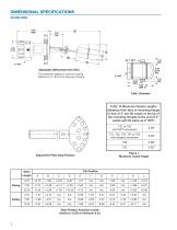
T31 AND T35: THREADED NARROW DIFFERENTIAL DIMENSIONS in mm (inches) T31: 220 (8.66) T35: 200 (7.86) ORDER CODE Process connection: 2" NPT Max temperature: switch selection dependant – see table on page 2 Max pressure: 50 bar abs. (720 psi) / 103 bar abs. (1500 psi) Level Differential: 13 mm (0,5") T 3 1 - 0 0 2 N T 3 5 - 0 0 2 N Threaded Tuffy with 316/316L (1.4401/1.4404) float - min. S.G. 0,4 / max 50 bar abs. ( 720 psi) Threaded Tuffy with 316/316L (1.4401/1.4404) float - min. S.G. 0,6 / max 103 bar abs. (1500 psi) DESIGN CODE (All wetted parts in 316/316L (1.4401/1.4404)) B Standard...
Open the catalog to page 4
ORDER CODE Process connection: up to 600 lbs ANSI / PN 63 anges Max temperature: switch selection dependant – see table on page 2 Max pressure: 50 bar abs. (720 psi) / 103 bar abs (1500 psi), or limited to ange rating. Level Differential: 13 mm (0.5") T 3 1 - 0 0 T 3 3 - 0 0 T 3 5 - 0 0 Flanged Tuffy with 316/316L (1.4401/1.4404) oat - min. S.G. 0,4 / max 50 bar abs. (720 psi) Flanged Tuffy with Hastelloy C (2.4819) oat - min. S.G. 0,65 / max 50 bar abs. (720 psi) Flanged Tuffy with 316/316L (1.4401/1.4404) oat - min. S.G. 0,6 / max 103 bar abs. (1500 psi) PROCESS CONNECTION – ANSI Flanges...
Open the catalog to page 5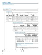
T32: FLANGED HIGH PRESSURE NARROW DIFFERENTIAL DIMENSIONS in mm (inches) 211 (8.29) ORDER CODE Process connection: up to 900 lbs ANSI / PN 160 flanges Max temperature: switch selection dependant – see table on page 2 Max pressure: 150 bar abs. (2160 psi) Level differential: 13 mm (0,5") T 3 2 - 0 0 Flanged Tuffy with 316/316L (1.4401/1.4404) float - min. S.G. 0,6 / max 150 bar abs. (2160 psi) PROCESS CONNECTION – ANSI Flanges 3 D 3" 900 lbs RF ANSI Flange 4 D 4" 900 lbs RF ANSI Flange PROCESS CONNECTION – EN/DIN Flanges A 4 DN 80, PN 100 EN 1092-1 Type B2 A 5 DN 80, PN 160 DIN 2527 Form E...
Open the catalog to page 6
T3C: ADJUSTABLE WIDE DIFFERENTIAL DIMENSIONS in mm (inches) Stem length (code 4): 327 (12.86) Stem length (code 8): 422 (16.61) Stem length (code C): 543 (21.36) Stem length (code 4): 346 (13.62) Stem length (code 8): 471 (18.54) Stem length (code C): 629 (24.76) Stem le Dimension "A Stem le ngth (code 4): " Stem le ngth (code 8): 95 (3.75) ngth (c ode C): 190 (7.50) 311 (12 .25) ORDER CODE Process connection: up to 300 lbs ANSI / PN 40 flanges Max temperature: switch selection dependant – see table on page 2 Max pressure: 50 bar abs. (720 psi) Level Differential: adjustable from 35 mm...
Open the catalog to page 7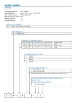
T3B: INTERFACE DIMENSIONS in mm (inches) 448 (17.62) ORDER CODE Process connection: up to 300 lbs ANSI / PN 40 flanges Max temperature: switch selection dependant – see table on page 2 Max pressure: 50 bar abs. (720 psi) Min S.G. of lower liquid: 0,81 kg/dm3 Min S.G. difference between both liquids: 0,1 kg/dm3 Level differential: 44 mm (1.72") T 3 B Interface Tuffy with 316/316L (1.4401/1.4404) float - max 50 bar abs. (720 psi) SPECIFIC GRAVITY OF LOWER LIQUID (consult factory for S.G. higher than 1.0 kg/dm3) 0,81 0,82 A B Specific Gravity Code Specific Gravity Code PROCESS CONNECTION – ANSI...
Open the catalog to page 8All Magnetrol - AMETEK catalogs and technical brochures
-
 Interface In The Field
14 Pages
-
 Emulsion In The Field
9 Pages
-
 PRODUCT LINE CATALOGUE
106 Pages
-
 Aurora® Magnetic Level Indicator
28 Pages
-
 Atlas™ Magnetic Level Indicator
24 Pages
-
 STEAM DRUM LEVEL MATTERS
1 Pages
-
 INTERFACE IN THE FIELD
1 Pages
-
 Echotel® 355
4 Pages
-
 Echotel® 335
4 Pages
-
 Power Generation
16 Pages
-
 Petroleum Refining
16 Pages
-
 Natural Gas Processing
12 Pages
-
 Seal Pots
4 Pages
-
 Mass Flow Measurement
12 Pages
-
 Interface Level Measurement
8 Pages
-
 Heat Rate Awareness
8 Pages
-
 Ethylene Applications
8 Pages
-
 Thermatel® TD1/TD2
16 Pages
-
 Kotron® 082
4 Pages
-
 Enhanced Jupiter®
16 Pages
-
 GEMINI™
32 Pages
-
 Aurora®
32 Pages
-
 Atlas™
24 Pages
-
 Horizon TM Model 704
8 Pages
-
 Eclipse® Enhanced 705 Hygienic
12 Pages
-
 Eclipse® Enhanced 705
8 Pages
-
 Pneumatic Tuffy®
12 Pages
-
 Models T5x & T6x
8 Pages
-
 Models T20/T21
12 Pages
-
 Series B73 and Series 75
12 Pages
-
 Series 3
24 Pages
-
 Model J52
2 Pages
-
 Model B40
4 Pages
-
 Digital E3 Modulevel®
12 Pages
-
 Floating Roof Detection
16 Pages
-
 APM Pneumatic Modulevel®
12 Pages
-
 Flue Gas Desulferization
8 Pages
-
 Energy Management
4 Pages
-
 API 2350 Overfill Prevention
8 Pages
-
 PULSAR ® R96
1 Pages
-
 Water & Wastewater
12 Pages
-
 Displacer Switches
20 Pages
-
 Displacer Transmitters
4 Pages
-
 Guided Wave Radar
12 Pages
-
 Magnetic Level Indicators
12 Pages
-
 Magnetostrictive
16 Pages
-
 Pulse Burst Radar
8 Pages
-
 Thermal Dispersion
12 Pages
-
 Ultrasonic Contact
4 Pages
-
 Vibrating Rod Switches
4 Pages
-
 R Series High Temp Switch
12 Pages
-
 Series K Pneumatic Switch
8 Pages
-
 J Series Pneumatic Switch
8 Pages
-
 Liquid Displacer Level Switches
16 Pages
-
 Crude Oil Processing
8 Pages
-
 Product Line Quick Reference
8 Pages


