- Catalogs
- Mindman Industrial
- MF01 / 02 series
MF01 / 02 series
1 /7Pages

MF01 / 02 series
1 /7Pages
Catalog excerpts
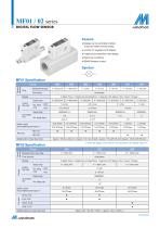
DIGITAL FLOW SENSOR Feature ● Display can be vertically inverted. To set and watch monitor easily. ● 3-Color & 7 segment LCD display. ● 8 digit accumulated flow rate display. ● Real-time monitoring. ● RS485 Modbus control. Sensor element Model Measured flow rate range Flow direction Unidirection 4 digital (Flow) / 8 digital (Accumulated flow), 7 segment LCD display ( Red / Green / Orange ) Display range Instant flow rate Switch outout Accumulated pulse output *1 Display range Accumulated Flow Port size Weight (with 2 meter lead wire) Approx. 109.3 g ( ø6 port ) ; Approx. 112.7 g ( ø8 port ); Approx. 118 g (Rc1/4 port); Approx. 128.5 g (Rc1/8 port) *1. When the display unit is CFM, ft3, the actual flow is the display value×10-2. MF02 Specification Sensor element Measured flow rate range Flow direction 4 digital (Flow) / 8 digital (Accumulated flow), 7 segment LCD display ( Red / Green / Orange ) Display range Instant flow rate Display range Accumulated flow Switch outout Accumulated pulse output *1 Port size
Open the catalog to page 1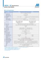
MF01 / 02 Specifications DIGITAL FLOW SENSOR Indicator accuracy Accuracy Guaranteed range Analog output accuracy Repeatability ± 5 % F.S. *1 ± 1 % F.S. ± 1 digit ( ± 2 % F.S. when response time is set to 50 ms ) *2 Linearity Temp. characteristic Pressure characteristic Switch output Switch output Response time Output mode ± 5 % F.S. ± 1 digit *3 2 NPN : open collector 2 outputs Max. Load Current : 125 mA Max. Supply Voltage : 28 V DC Voltage Drop : ≤ 1.5 V 2 PNP : open collector 2 outputs Max. Load Current : 125 mA Max. Supply Voltage : 24 V DC Voltage Drop : ≤ 1.5 V 800 ms ( 50 ms, 80 ms, 120...
Open the catalog to page 2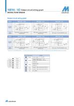
MF01 / 02 Output circuit wiring graph DIGITAL FLOW SENSOR Output circuit wiring graph MF01/02-□-010 Power supply (+) (Brown) Analog output (Orange) External input (Yellow) Load External input (Yellow) Main circuit Main circuit Connect diagram Power supply (+) (Brown) Power supply (+) (Brown) Analog output (Orange) Power supply (–) (Blue) Main circuit Output 2 (White) Power supply (–) (Blue) Power supply (–) (Blue) Output method NPN output / Analog voltage output / External input NPN output / Analog current output / External input NPN output / RS-485 MODBUS mode Power supply (+) (Brown) Power...
Open the catalog to page 3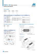
MF01 / 02 Order example DIGITAL FLOW SENSOR Order example OUTPUT METHOD FLOW RATE RANGE PORT SIZE 010: 2 NPN output + 1 Analog output (1~5V) 011: 2 NPN output + 1 Analog output (4~20mA) 02 : 2 NPN output + RS485 030: 2 PNP output + 1 Analog output (1~5V) 031: 2 PNP output + 1 Analog output (4~20mA) 04 : 2 PNP output + RS485 Mounting accessories Name and functions of individual parts Panel description Flow direction symbol Flow unit display section OPTION PARTS A27: Mounting bracket, for 501, 102 A28: Mounting bracket, for 202 A26: Mounting bracket B4: Panel adapter C4: Panel adapter + Front protective...
Open the catalog to page 4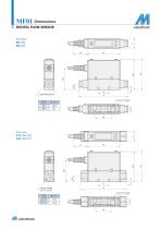
DIGITAL FLOW SENSOR Code Thread
Open the catalog to page 5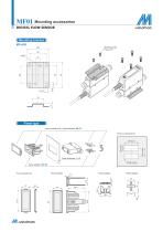
MF01 Mounting accessories DIGITAL FLOW SENSOR Mounting screw P type 3×6 Panel type Front protective lid + Panel adapter MP-C4 Panel cut dimensions Panel thickness 1~4.5 4×R3 or less Panel adapter Panel adapter Panel adapter
Open the catalog to page 6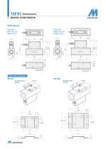
DIGITAL FLOW SENSOR
Open the catalog to page 7All Mindman Industrial catalogs and technical brochures
 MCTC series
7 Pages
 MPDS series
4 Pages
 MPGS series
4 Pages
 MCQVS
MCQVS11 Pages
 MSEBE
MSEBE4 Pages
 E_MCJQ-3
5 Pages
 MVB-156
3 Pages
 MVB-100
3 Pages
 MVSP-188
4 Pages
 MVSP-156
5 Pages
 MVSN-300
3 Pages
 MVSN-220
2 Pages
 MVSI-510
2 Pages
 MVSI-450
2 Pages
 MVSI-260
2 Pages
 MVSE-500
2 Pages
 MVSE-300
3 Pages
 MVSE-260
3 Pages
 MVSC1-220
5 Pages
 MVSC1-180
4 Pages
 MVSC1-150
2 Pages
 MVSC-400
4 Pages
 MVSC-300
4 Pages
 MVSC-260
3 Pages
 MVSC-220
5 Pages
 MVSY-188
5 Pages
 MVSY-156
6 Pages
 MVSY-100
4 Pages
 MCJA Back
3 Pages
 MP70
MP704 Pages
- SARRALLE valve
- SARRALLE connector
- SARRALLE manual valve
- SARRALLE control valve
- SARRALLE cylinder
- SARRALLE actuator
- SARRALLE solenoid valve
- Liquid filter
- SARRALLE linear actuator
- SARRALLE electric actuator
- SARRALLE gas solenoid valve
- SARRALLE NC solenoid valve
- SARRALLE 2-way solenoid valve
- SARRALLE direct-operated solenoid valve
- SARRALLE pressure regulator
- Directional control valve
- Double-acting cylinder
- Hydraulic cylinder
- Industrial connector
- SARRALLE single-stage pressure regulator