- Catalogs
- Milton Roy
- 339-0083-000 5-2005 Electronic Capacity Control
339-0083-000 5-2005 Electronic Capacity Control

339-0083-000 5-2005 Electronic Capacity Control
1. PCB Installation: Connect connectors J1 to J5 to the bottom of the PCB. Place the PCB on standoffs and tighten screws with nylon washers. Perform calibration B or C based on factory calibration status.
2. Feedback Potentiometer Replacement: Removal: Set pump stroke to 0%, disconnect power, remove PCB, and unscrew potentiometer assembly. Installation: Align and install the new potentiometer, apply lithium grease if needed, compare wire colors, and install jumper cable if necessary. Reinstall PCB and perform calibration A.
3. Nylon Worm Gear Replacement: Removal: Set pump stroke to 0%, disconnect power, remove PCB and potentiometer, and remove the nylon gear. Installation: Align and install the new gear, reinstall capacitor, potentiometer, and PCB, and perform calibration A.
4. Motor Replacement: Removal: Set pump stroke to 0%, disconnect power, remove ECC, gearbox, and motor components. Installation: Mount the new motor, connect wires, install worm gear, attach adapter plate, apply grease, and perform calibration A.
5. ECC Calibration: Calibration A: Synchronize ECC with pump after component replacement. Use a digital volt meter and adjust potentiometers for zero and span settings. Calibration B: Synchronize ECC with pump after replacing a factory-calibrated circuit board. Calibration C: Complete calibration for a new, non-factory-calibrated circuit board. Used for diagnostics and setup for different pump series.
Warnings: Always disconnect electrical power before maintenance to prevent injury. Calibration involves working with high voltages and should be performed by qualified personnel.
Catalog excerpts

THIS PAGE INTENTIONALLY BLANK >
Open the catalog to page 2
WHEN INSTALLING, CALIBRATING, OR OPERATING THIS ACTUATOR, BASICSAFETY PRECAUTIONS SHOULD ALWAYS BE FOLLOWED TO REDUCE RISK OF FIRE, ELECTRIC SHOCK, AND PERSONAL INJURY. FAILURE TO FOLLOW THESE INSTRUCTIONS COULD RESULT IN DEATH OR SERIOUS INJURY.Read all instructions before installation, calibration, or operationGENERAL SAFETY CONSIDERATIONS - Read this manual carefully. - Installation, calibration, and maintenance should be performed by trained and qualified personnel. Per-sonnel should be familiar with the precautions required in working with hazardous voltages which existinside the actuator....
Open the catalog to page 3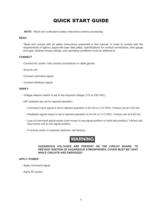
NOTE: Read and understand safety instructions before proceeding READ - Read and comply with all safety instructions presented in this manual. In order to comply with therequirements of agency approvals (see data plate), specifications for conduit connections, wire gaugeand type, fastener torque ratings, and operating conditions must be adhered to. CONNECT VERIFY - Connect AC power. Use conduit connections or cable glands. - Ground unit. - Connect command signal.- Connect feedback signal. - Voltage selector switch is set to the required voltage (115 or 230 VAC).- DIP switches are set for desired...
Open the catalog to page 4
OBSERVE - Actuator should run to command position and stop.- Full range of command signal should result in desired range of actuator travel (factory setting is for fulltravel of 0% to 100%). CALIBRATE - If actuator was installed on the pump at the factory, it has been factory calibrated.- If actuator is a retrofit or a non-standard range is desired, follow the calibration instructions in this man-ual. FINISH - Install cover. Observe torque requirements of 15 ft.-lb. (20 N-m) in hazardous locations. iii >
Open the catalog to page 5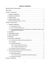
IMPORTANT SAFETY INSTRUCTIONS . . . . . . . . . . . . . . . . . . . . . . . . . . . . . . . . . . . . . . . . . . . . . . . . . . .iQUICK START . . . . . . . . . . . . . . . . . . . . . . . . . . . . . . . . . . . . . . . . . . . . . . . . . . . . . . . . . . . . . . . . . . . . . . iiSECTION 1 - DESCRIPTION . . . . . . . . . . . . . . . . . . . . . . . . . . . . . . . . . . . . . . . . . . . . . . . . . . . . . . . . . . . 11.1 GENERAL INFORMATION. . . . . . . . . . . . . . . . . . . . . . . . . . . . . . . . . . . . . . . . . . . . . . . . . . . . . . 11.2 PRINCIPLE OF OPERATION . . . . . ....
Open the catalog to page 6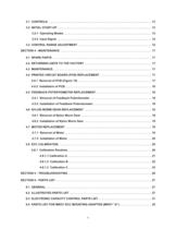
3.1 CONTROLS . . . . . . . . . . . . . . . . . . . . . . . . . . . . . . . . . . . . . . . . . . . . . . . . . . . . . . . . . . . . . . . . 133.2 INITIAL START-UP. . . . . . . . . . . . . . . . . . . . . . . . . . . . . . . . . . . . . . . . . . . . . . . . . . . . . . . . . . . 133.2.1 Operating Modes. . . . . . . . . . . . . . . . . . . . . . . . . . . . . . . . . . . . . . . . . . . . . . . . . . . . . . . 133.2.2 Input Signal . . . . . . . . . . . . . . . . . . . . . . . . . . . . . . . . . . . . . . . . . . . . . . . . . . . . . . . . . . . 143.3 CONTROL RANGE ADJUSTMENT . . . . . . . ....
Open the catalog to page 7
6.5 PARTS LIST FOR MROY ECC MOUNTING ADAPTER (MROY BӔ). . . . . . . . . . . . . . . . . . . . 376.6 PARTS LIST FOR MACROY ECC MOUNTING ADAPTER (MACROY GӔ, DӔ AND MIL-ROYAL G) . . . . . . . . . . . . . . . . . . . . . . . . . . . . . . . . . . . . . . . . . . . . . . . . . . . . . . . . . . . . . . . . . . 406.7 PARTS LIST FOR MAXROY ECC MOUNTING ADAPTER (MAXROY BӔ). . . . . . . . . . . . . . . 436.8 PARTS LIST FOR MILROYAL ECC MOUNTING ADAPTER AND MOUNTING ADAPTER GUARD ASSEMBLY (MILROYAL BӔ) . . . . . . . . . . . . . . . . . . . . . . . . . . . . . . . . . . . . . . . . . . . 476.9 PARTS LIST...
Open the catalog to page 8
Table 1. Stroke Adjust Shaft & Pump Opera-tion Reference ManualsPUMPMANUAL 1.1 GENERAL INFORMATION In this age of sophisticated process control con-cepts, many people are taking advantage of the lat-est breakthroughs in technology to upgrade theirown equipment and systems. The Milton Roy Elec-tronic Capacity Control (ECC) easily interfaces with computerized process and process instruments, asthe ECC will adjust the output of a metering pump from 0% to 100% in response to a 4 to 20 milliamp or 1 to 5 VDC signal from a computer or other source. This outstanding feature can be purchasedas an integral...
Open the catalog to page 9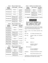
Table 5. Milroyal C Model CodesMODELNUMBERENCLOSUREVOLTAGE PPGW482LMHNema 4115 VAC50/60 HzPPGW682LMHNema 4230 VAC60 HzPPGW782LMHNema 4230 VAC50 HzPPGX482LMHExplosion Proof(FM Approved)115 VAC50/60 HzPPGX682LMHExplosion Proof (FM Approved)230 VAC60 HzPPGX782LMHExplosion Proof (FM Approved)230 VAC50 Hz Table 8. MacRoy D and G Model CodesMODELNUMBERENCLOSUREVOLTAGE50/60 HZ PPGW242LMHNema 4115 VACPPGW542LMHNema 4230 VAC PPGX242LMHExplosion Proof (FM Approved)115 VACPPGX542LMHExplosion Proof (FM Approved)230 VAC 1.5 AGENCY APPROVALS (Figures 1, 2 and 3) Table 6. Milroyal D Model CodesMODELNUMBERENCLOSUREVOLTAGE50/60...
Open the catalog to page 11
Figure 1. Nema 4 Electronic Capacity Control Data Plate. Figure 2. Nema 7 Electronic Capacity Control Data Plate. DECLARATION OF CONFORMITY Application of Council Directive(s): LVD 73/23/EEC as amended by 93/68/EEC; EMC 89/336/EEC as amended by 91/263/EEC and 92/31/EEC, and CENELEC ATEX 94/9/EG. Standards to which Conformity is Declared: LVD: EN61010 EMC: EN50081 and EN50082 CENELEC: EN50014 and EN50018 Declarer's Name/Address: Milton Roy Company - Flow Control Division 201 Ivyland Road Ivyland, PA 18974 USA Type of Equipment: Industrial Actuators Model Number: All "P" series hazardous location....
Open the catalog to page 12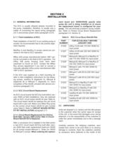
Table 9. ECC C board (p/n 30300/39320) specify whatpump the unit is being installed on to insure the replacement board is configured for yourpump. This will eliminate problems during installa-tion. Refer to Printed Circuit Board Replacement (paragraph 4.4, Section 4 ) > 2.1 GENERAL INFORMATION The ECC is usually shipped already mounted tothe pump. Installation, therefore, is usually only a matter of connecting the signal wiring (paragraph2.6.1) and primary power wires (paragraph 2.6.4). 2.1.1 Field Installation of ECC Field installation of the ECC to an existing pump isusually not recommended...
Open the catalog to page 13All Milton Roy catalogs and technical brochures
 Proteus
8 Pages
 POWEROYAL®
8 Pages
 Primeroyal
8 Pages
 mROY
mROY7 Pages
 PD3621 Milroyal D 9-96
4 Pages
 mRoy 3300 Brochure
16 Pages
 Primeroyal X brochure
4 Pages
 SOLAROY Brochure
4 Pages
 Streaming Current Detectors
4 Pages
 MaxRoy B Pumps
2 Pages
 SC5200
2 Pages
 Milroyal C
12 Pages
 Milroyal B
12 Pages
 Electronic Capacity Control
4 Pages
 Milroyal G Metering Pumps
2 Pages
 Milroyal D Pumps
4 Pages
 Calibration Column
2 Pages
 RoyPak
2 Pages
 PrimeRoyal Brochure
8 Pages


Archived catalogs
 339-0047-000 8/00 mRoy A and B
72 Pages
 Milton Roy mRoy Brochure #3300
12 Pages


- SARRALLE industrial pump
- SARRALLE electric pump
- SARRALLE stationary pump
- SARRALLE water pump
- SARRALLE self-priming pump
- SARRALLE chemical pump
- SARRALLE lubricant pump
- SARRALLE dynamic mixer
- SARRALLE oil pump
- Submersible pump
- SARRALLE pump for the chemical industry
- Diaphragm pump
- Compact pump
- SARRALLE high-flow pump
- Mechanical pump
- SARRALLE rugged pump
- SARRALLE standard pump
- Cast iron pump