- Catalogs
- Milton Roy
- 339-0047-000 8/00 mRoy A and B
339-0047-000 8/00 mRoy A and B

339-0047-000 8/00 mRoy A and B
- Introduction: The mRoy pump is a reliable, controlled volume pump with a hydraulically actuated diaphragm design, available in two frame sizes, mRoy A and mRoy B.
- General Information: The pump's capacity can be adjusted manually or automatically, maintaining a repetitive accuracy within ±1% under constant conditions. It is suitable for handling corrosive or toxic chemicals and light slurries with viscosities up to 200 S.S.U. (40 cps).
- Pump Characteristics: Utilizes a plunger to displace hydraulic fluid, actuating a PTFE diaphragm. Double ball check valves ensure metering accuracy, with capacity control achieved by adjusting the hydraulic fluid volume.
- Pump Performance: Consistent metering accuracy is maintained by keeping the hydraulic oil volume constant, with mechanisms for air or vapor bleeding, oil replenishment, and temperature-induced oil volume changes.
- Unpacking/Inspection: Guidelines for safely unpacking and inspecting the pump upon delivery.
- Safety Precautions: Important safety measures during installation and operation.
- Pump Mounting/Location: Recommendations for optimal pump placement and mounting.
- Outdoor Installations: Special considerations for outdoor installations.
- Electrical Connections: Instructions for safe and correct electrical connections.
- Initial Start-Up: Steps for first-time operation of the pump.
- Resetting the Relief Valve: Procedure for adjusting the relief valve.
- Spare Parts: Information on available spare parts.
- Routine Maintenance: Regular maintenance tasks to keep the pump in optimal condition.
- Corrective Maintenance: Procedures for replacing components like check valve cartridges, diaphragms, and motors.
- Guide to diagnosing and resolving common pump issues.
- Illustrated parts list and descriptions for various models and components.
- Details of the warranty coverage provided for the pump.
Detailed description of the mRoy pump, including model numbers and product codes.
Performance charts for mRoy A & B frame pumps, with a derating table for specific conditions.
The mRoy pump operates using four main components: a reciprocating pump plunger, a flexible diaphragm, an oil bypass circuit, and a bypass control plunger.
The pump offers ±1% steady state accuracy over a 10:1 turndown, featuring a hydraulic bypass design and high-performance check valves.
Various model codes for different series with options for liquid end materials, plunger diameters, gear ratios, motor mounts, and connection types.
Tables for different models showing capacities and pressures in GPH, with notes on derating.
Maintenance kits listed by model code, with options for different materials and configurations.
Options for rupture detection and base configurations, with specific codes for metallic and plastic liquid ends.
Table to adjust capacities based on specific options like electronic or pneumatic capacity control.
Flanged connections recommended, with specific connection sizes for different series.
Various control options available, including manual, electronic, and pneumatic.
Options for rupture detection include gauges and switches, with configurations for metallic and plastic liquid ends.
Maintenance kits specified by model and liquid end material.
Guidelines for unpacking, safety precautions, pump mounting, and electrical connections.
Standard motors provide adequate power, with precautions for ventilation and overload protection.
Proper oil levels are crucial, with recommendations for synthetic oils.
Proper support and stress-free connections are essential, with recommendations for suction and discharge piping.
Guidelines for operating with less than atmospheric pressure.
Steps for initial start-up, including checking oil levels and setting capacity controls.
Steps for listening for abnormal noises, warming up oil, and adjusting capacity.
Procedure for adjusting the internal relief valve.
Regular checks for oil levels and leaks, maintaining spare parts, and performing yearly tune-ups.
Procedures for disconnecting power, replacing check valve cartridges, and following specific disassembly instructions.
Guidelines for disassembly, cleaning, and reassembly of valves.
Disassembly and reassembly instructions for plastic liquid ends.
Instructions for disassembly and reassembly of relief valve components.
Instructions for disassembly and reassembly of diaphragms.
Common issues and remedies for pump operation.
Illustrated parts list with item numbers, descriptions, and part numbers.
Detailed list of parts for various drive models, including part numbers and materials.
List of parts shared among models, focusing on durability and chemical resistance.
Details on diaphragm head designs for different models.
Components for motor mounts, covering different mounting standards.
Details on electronic capacity control kits, emphasizing precision and control.
Detailed list of parts, including descriptions, part numbers, materials, and quantities.
Limited warranty covering defects in title, materials, and workmanship for twelve months.
Specifications for the mRoy L pump, including plunger diameter options and capacity range.
Contact details for the Milton Roy Company.
Catalog excerpts

THIS PAGE INTENTIONALLY BLANK >
Open the catalog to page 2
SECTION 1 - GENERAL DESCRIPTION. . . . . . . . . . . . . . . . . . . . . . . . . . . . . . . . . . . . . . . . . . . . . . . . . . . . . . . . 1 1.1 INTRODUCTION . . . . . . . . . . . . . . . . . . . . . . . . . . . . . . . . . . . . . . . . . . . . . . . . . . . . . . . . . . . . . . . . . . . . 11.2 GENERAL INFORMATION . . . . . . . . . . . . . . . . . . . . . . . . . . . . . . . . . . . . . . . . . . . . . . . . . . . . . . . . . . . . 11.3 PUMP CHARACTERISTICS . . . . . . . . . . . . . . . . . . . . . . . . . . . . . . . . . . . . . . . . . . . . . . . . . . . . . . . . . . . 11.4 PUMP PERFORMANCE...
Open the catalog to page 3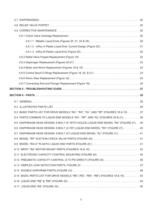
SECTION 5 - TROUBLESHOOTING GUIDE. . . . . . . . . . . . . . . . . . . . . . . . . . . . . . . . . . . . . . . . . . . . . . . . . . . . . 27SECTION 6 - PARTS. . . . . . . . . . . . . . . . . . . . . . . . . . . . . . . . . . . . . . . . . . . . . . . . . . . . . . . . . . . . . . . . . . . . . . . 29 6.1 GENERAL. . . . . . . . . . . . . . . . . . . . . . . . . . . . . . . . . . . . . . . . . . . . . . . . . . . . . . . . . . . . . . . . . . . . . . . . . 296.2 ILLUSTRATED PARTS LIST . . . . . . . . . . . . . . . . . . . . . . . . . . . . . . . . . . . . . . . . . . . . . . . . . . . . . . ....
Open the catalog to page 4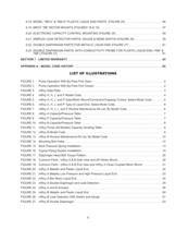
SECTION 7 - LIMITED WARRANTY . . . . . . . . . . . . . . . . . . . . . . . . . . . . . . . . . . . . . . . . . . . . . . . . . . . . . . . . . . 63APPENDIX A - MODEL CODE HISTORY . . . . . . . . . . . . . . . . . . . . . . . . . . . . . . . . . . . . . . . . . . . . . . . . . . . . . . .65 > FIGURE 1.Pump Operation With By-Pass Port Open . . . . . . . . . . . . . . . . . . . . . . . . . . . . . . . . . . . . . . . . . . . . .2FIGURE 2.Pump Operation With By-Pass Port Closed. . . . . . . . . . . . . . . . . . . . . . . . . . . . . . . . . . . . . . . . . . . .2FIGURE 3.mRoy Data Plate. . . . ....
Open the catalog to page 5
THIS PAGE INTENTIONALLY BLANK iv >
Open the catalog to page 6
1.3 PUMP CHARACTERISTICS For a general description of the mRoy pump you havepurchased, compare the model number and productcode printed on the pumps data plate (shown in Figure3) to the appropriate model number and product codeshown in Figures 4 through 6 and Figure 12. 1.4 PUMP PERFORMANCE The charts in Figures 8 through 10 show the perfor-mance ranges for all mRoy A & B frame pumps. If appropriate, refer also to the derating table shown inFigure 11. 1.5 PRINCIPLE OF OPERATION Pumping action is developed and controlled by fourbasic components as follows (Figures 1 & 2):1.The pump plunger ғA...
Open the catalog to page 7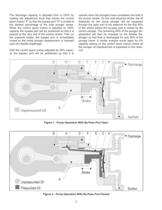
Figure 1. Pump Operation With By-Pass Port Open Figure 2. Pump Operation With By-Pass Port Closed 2 The discharge capacity is adjusted from 0100% byrotating the adjustment knob that moves the controlspool (valve) ֓F so that the bypass port ԓH is closed atthe desired percentage of the total plunger stroke.When the control spool (valve) is adjusted to 100%capacity the bypass port will be positioned so that it isopened at the very end of the suction stroke. Then onthe pressure stroke, the bypass port is immediately closed so the entire plunger displacement is imposedupon the flexible diaphragm....
Open the catalog to page 8
END ITEM AND OPTION SELECT NUMBER > R A 1* > MaterialCode DiameterSetMotorConnectionEnd item Model CodeOption Select NumberPlungerGearMount /SuctionDischargeCapacityRupture ControlDetection& Base * 2 for Duplex mRoy A LIQUID END MATERIAL CODE SELECTIONCodeDescription 0Cast Iron 1 316 SS (STANDARD) 2PVC (N/A with 9.5:1 Gear Ratio)7PVDF (N/A with 9.5:1 Gear Ratio) 5 A lloy 206 A lloy C22 mRoy A PLUNGER DIAMETERCodeDescription 077/16" Diameter105/8" Diameter 171-1/16" Diameter > End Item Model CodeOption Select Number RH1 - MaterialCodemRoy H LIQUID END MATERIALCodeDescription r Mount /SetMoto r...
Open the catalog to page 10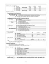
STANDARD MOTOR with Close Coupled flan g eCodeDescription A 1 1/4 HP Motor, TE, 1725 RPM, 1 Phase, 60 Hertz, 115 Volt & Close Coupled Flan g e A 8 1/4 HP Motor, TE, 1725 RPM, 3 Phase, 60 Hertz, 230/460 Volt & Close Coupled Flan g e Note: These motors replace the obsolete inte g ral motor offerin g . They are standardNEMA 56 C frame motor on a short flan g e. > 1/4 HP minimum. CodeDescriptionSR Close Coupled Flan g e, NEMA 56C (STANDARD) SSClose Coupled Flan g e, IEC Frame 71, B5 Flan g eFR A PI Flan g e Mount, NEMA 56CF4 A PI Flan g e Mount, NEMA 143TC/145TCFS A PI Flan g e Mount, IEC Frame 71,...
Open the catalog to page 11
RUPTURE DETECTION & BASE (mRoy A FRAME)Metallic Liquid EndsCodeDescription NNNone ( STANDARD )NBBase Only - Recommended with FlangesC5Rupture Detection with Base & Gauge N/A on RH SNRupt. Detect. w/ Base, Gauge, & NEMA 4 Switch N/A on RH S7Rupt. Detect. w/ Base, Gauge, & Ex. Prf Switch N/A on RH DDDouble Diaphragm with Base N/A on RH or RJ DPDouble Diaphragm with Base & Conductivity Probe Relay supplied separately - see accessory pricing Plastic Liquid EndsCodeDescription NBBase Only ( STANDARD )DDDouble Diaphragm with BaseDPDouble Diaphragm with Base & Conductivity Probe Relay supplied separately...
Open the catalog to page 12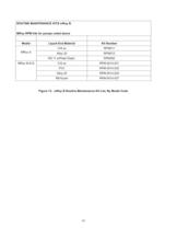
MRoy S316 ssRPM011Alloy 20RPM012RS 11 w/Peek Diaph.RPM092MRoy M & B316 ssRPM-0014-021PVCRPM-0014-032Alloy 20RPM-0014-025RB KynarRPM-0014-037 Figure 13. mRoy B Routine Maintenance Kit List, By Model Code ROUTINE MAINTENANCE KITS mRoy BMRoy RPM kits for pumps noted aboveModelLiquid End MaterialKit Number 10 >
Open the catalog to page 16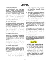
2.5 FLANGE MOUNTED MOTORS If a flange mounted motor option was selected for themRoy pump, the customer supplied motor will need to be mounted to the pump. This is generally a straightforward procedure. Refer to Figure 18 or 19, as appro-priate.When mounting the motor to a NEMA 56C Close Cou-pled Flange (product code option SR, refer to Figure19), the motor mount plate (710) must be removed from the pump body and bolted to the motor. The motor/motor mount plate assembly can then be bolted to the pump. > 2.6 ELECTRICAL CONNECTIONS 2.1 UNPACKING/INSPECTION Check to be sure that the electrical supply...
Open the catalog to page 17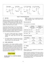
Oil TypeAmbient Temp. 15-50 F (-9-10 аC)Ambient Temp. Above 50F (10 аC) Figure 14. Mounting Bolt Holes Any equivalent oil is acceptable. NOTE: Synthetic oils are available that span theentire temperature range. Contact Milton Roy for further information. 2.7 MOTORS Recommended Oil AGMA Spec No. 2 EPNo. 5 EPZurn Oil Co No. EP 35No. EP 95 ISO Grade68220 Adequate power is provided to the simplex mRoy Apump by the standard HP (0.2 Kw) motor. The motoris normally a totally enclosed non-ventilated, type, thatis mounted on a 56C-face flange or IEC Frame 71 flange. The gear reducer (worm shaft) fits...
Open the catalog to page 18All Milton Roy catalogs and technical brochures
 Proteus
8 Pages
 POWEROYAL®
8 Pages
 Primeroyal
8 Pages
 mROY
mROY7 Pages
 PD3621 Milroyal D 9-96
4 Pages
 mRoy 3300 Brochure
16 Pages
 Primeroyal X brochure
4 Pages
 SOLAROY Brochure
4 Pages
 Streaming Current Detectors
4 Pages
 MaxRoy B Pumps
2 Pages
 SC5200
2 Pages
 Milroyal C
12 Pages
 Milroyal B
12 Pages
 Electronic Capacity Control
4 Pages
 Milroyal G Metering Pumps
2 Pages
 Milroyal D Pumps
4 Pages
 Calibration Column
2 Pages
 RoyPak
2 Pages
 PrimeRoyal Brochure
8 Pages


Archived catalogs
 Milton Roy mRoy Brochure #3300
12 Pages


- SARRALLE industrial pump
- SARRALLE electric pump
- SARRALLE stationary pump
- SARRALLE water pump
- SARRALLE self-priming pump
- SARRALLE chemical pump
- SARRALLE lubricant pump
- SARRALLE dynamic mixer
- SARRALLE oil pump
- Submersible pump
- SARRALLE pump for the chemical industry
- Diaphragm pump
- Compact pump
- SARRALLE high-flow pump
- Metering pump
- Mechanical pump
- SARRALLE rugged pump
- SARRALLE standard pump
- Cast iron pump