- Catalogs
- Milesight IoT
- Cellular Remote I/O
- Company
- Products
- Catalogs
- News & Trends
- Exhibitions
Cellular Remote I/O
1 /28Pages

Cellular Remote I/O
1 /28Pages
Catalog excerpts
UC3x14 series User Guide
Open the catalog to page 2
UC3x14 series User Guide Thank you for choosing Ursalink UC3x14 Cellular Remote I/O. This user guide will present in detail all the functions and features of the product. The Ursalink UC3x14 is designed for both industrial and commercial applications. The product should be used under the guidance of this user guide, referring to parameters and technical specifications. The UC3x14 series is a compact, high-performance device that offers remote controllability and easy management of machines and equipment over the cellular network. We bear no liability for property loss or physically injury arising...
Open the catalog to page 3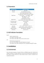
UC3x14 series User Guide 2.3 LED Indicator Description System: Solid On: Equipment starts On for 500ms, off for 500ms: All OK On for 100ms, off for 100ms: Device cannot connect to server ACT Off: GSM engine registration fails On for 75ms, off for 3000ms: Successfully registered on network On for 500ms, off for 500ms, blinking three times: Sending/Receiving MQTT message 3. Installation 3.1 Environment Due to the product properties of Ursalink UC3x14, we STRONGLY advise that it should not be installed in proximity to a variable speed drive or with any other electrically noisy equipment. DO NOT...
Open the catalog to page 4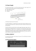
UC3x14 series User Guide 3.2 Power Supply The Ursalink UC3x14 features a 2 pin 3.5mm terminal block where a power supply can be connected. The power supply should have the following specifications: Output Voltage: 12V nominal Output Current: 0.5A Installation: A suitable power supply comes with the product. For industrial applications, it is advised that the Ursalink UC3x14 should be installed into its own metal housing and be powered from a separate power supply (as opposed to sharing one with other equipment). Please Note: While the Ursalink UC3x14 has fairly rugged internal power supply...
Open the catalog to page 5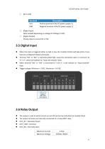
UC3x14 series User Guide
Open the catalog to page 6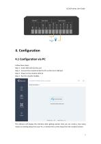
UC3x14 series User Guide 4. Configuration4.1 Configuration via PC Follow these steps: Step 1: Insert SIM card into the unit. Step 2: Connect the Ursalink UC3x14 to PC via the micro USB port. Step 3: Power on the Ursalink UC3x14. Step 4: Run the Ursalink ToolBox. Firmware Version: 01.08 Hardware Version VI .01 The software will display this interface when getting started. Here you can create a new setup, import an existing setup from your PC, or retrieve the current setup from the Ursalink UC3x14.
Open the catalog to page 7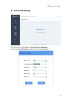
UC3x14 series User Guide 4.1.1 Serial Port Settings When the Ursalink ToolBox displays: Connecting to device, please wait... You can click Serial Port Settings to set the correct serial port parameters.
Open the catalog to page 8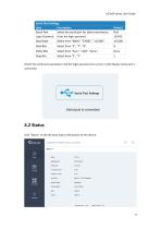
UC3x14 series User Guide Serial Port Settings Item Description Serial Port Select the serial port for data transmission. Default Null Login Password Enter the login password. Baud Rate Data Bits Parity Bits Select from "Even", "Odd", "None". Stop Bits If both the serial port parameters and the login password are correct, it will display: Serial port is connected. 4.2 Status Click "Status" to see the basic status information of this device:
Open the catalog to page 9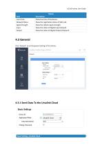
UC3x14 series User Guide Status Item Local Time Network Status Signal Strength Input Output Description Show the time of the device. Show the registration status of SIM card. Show the cellular signal strength. Show the status of Digital Input1/Input2. Show the status of Digital Output1/Output2. 4.3 General Click "General" to set the general settings of this device: 4.3.1 Send Data To the Ursalink Cloud Basic Settings_Ursalink Cloud
Open the catalog to page 10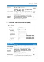
UC3x14 series User Guide
Open the catalog to page 11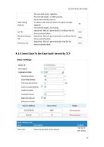
UC3x14 series User Guide Data Polling Interval CA File Client Certificate File Client Key File the user-built server regularly. The interval range is 1-1440 seconds. Set the Data Polling interval. The device will read I/O status and signal strength regularly. The interval range is 30 seconds. Upload the AWS IoT-generated CA certificate file for device authentication. Upload the AWS IoT-generated client certificate file for device authentication. Upload the AWS IoT-generated client key file for device authentication. Null Null Null 4.3.3 Send Data To the User-built Server By TCP Basic Settings_TCP...
Open the catalog to page 12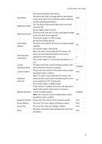
UC3x14 series User Guide
Open the catalog to page 13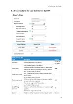
UC3x14 series User Guide
Open the catalog to page 14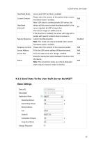
UC3x14 series User Guide
Open the catalog to page 15
UC3x14 series User Guide Select the authentication method required by the server. When you select user credentials for authentication, you need to enter the username and password required for authentication.
Open the catalog to page 16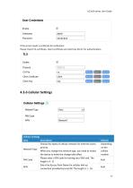
TLS Enable Protocol CA File Client Certificate Client Key Cellular Settings
Open the catalog to page 17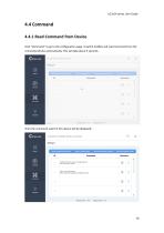
UC3x14 series User Guide 4.4 Command 4.4.1 Read Command from Device Click "Command" to go to the configuration page. Ursalink ToolBox will read command from the connected device automatically. This will take about 5 seconds. Then the command saved in this device will be displayed:
Open the catalog to page 18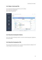
UC3x14 series User Guide 4.4.2 Open a Command File You can import the existing command file from your PC as follows: Step 1: Click "Open a Command File". Step 2: Select the command file. 4.4.3 Save the Command to Device You can click "Save the Command to Device" to save the command having been configured on the Ursalink ToolBox. 4.4.4 Save the Command as File You can click "Save the Command as File" to save the command having been configured on the Ursalink ToolBox as a file and save it on your computer.
Open the catalog to page 19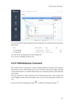
UC3x14 series User Guide You can re-edit the file name and determine the storage path, the command will be saved as two types of files. The ".dat" file can be recognized by Ursalink ToolBox only. The ".txt" file is an editable text file for user. 4.5 IF-THEN Behaviour Command The Ursalink UC3x14 is running with a number of defined behaviour commands. Each command takes the form of an IF-THEN statement pair. You are thus able to select certain trigger conditions to cause desired actions. The Ursalink UC3x14 allows up to 8 separate behaviour commands with some models. Users can select time or input...
Open the catalog to page 20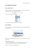
UC3x14 series User Guide A command containing this IF condition will be triggered at a specific time every day within a specified range of dates, or on every selected day of the week. The user can choose the day of the week from: luesday Wednesday Thursday Friday Saturday Sunday _ The user can also set the time from 00:00 to 23:59 on a certain day. 4.5.1.2 IF Input A command containing this IF condition will be triggered if the selected input changed according to the specified option. The user can setup multiple combinations; however, input 1 and input 2 must be activated before action is taken....
Open the catalog to page 21All Milesight IoT catalogs and technical brochures
 UC3xSeries
3 Pages
 UR755G
6 Pages
 UR35
UR356 Pages
 UR32
UR326 Pages
 UG65
UG655 Pages
 AI Speed Dome Network Camera
4 Pages
 Ursalink LoRaWAN Starter Kit
5 Pages
 Ursalink IoT Cloud
6 Pages
 EM500 PT100 LoRaWAN Sensor
26 Pages
 Ursalink Product Catalog
10 Pages
 Cellular/NB-IoT Remote IO
3 Pages
 Success Stories-School Bus
2 Pages
 UC11-N1 LoRaWAN Sensor Nod
5 Pages
 Ursalink-UC11-T1-Temp Sensor
2 Pages
 Ursalink-UC-11-N1
2 Pages
 Ursalink Product Catalogue
18 Pages
 IoT Edge Gateway
6 Pages
 LoRa Remote I/O
3 Pages
 UC1114
2 Pages
 SMS Remote I/O
2 Pages
 UR51 52 55 Industrial Router
2 Pages
 UR71 72 75 Industrial Router
2 Pages
 UR75
UR752 Pages
 UC Remote IO Controller
2 Pages
 UG87 LoRaWAN Gateway
2 Pages
 UC1214
2 Pages
 UR75
UR756 Pages
 UR72
UR726 Pages
 UR71
UR716 Pages
 UR55
UR556 Pages
 UR52
UR526 Pages
 UG87-LW
147 Pages
 Ursalink UR51 Datasheet
6 Pages
 DeviceHub Datasheet
3 Pages
 UrsalinkVPN Datasheet
3 Pages
 UG87 Gateway Datasheet
4 Pages


- Temperature probe
- Transformer
- Dry transformer
- Data logger
- Resistance temperature sensor
- Single-pole switch
- Real-time software
- Cloud-based software
- Level probe
- Color display panel
- Push-button switch
- Liquid level sensor
- Pressure probe
- Technology switch
- LED display panel
- Communication gateway
- Current transformer
- Interface software
- Waterproof temperature sensor