
- Catalogs
- Miki Pulley Europe AG
- Spring-Actuated Brakes


Spring-Actuated Brakes

Spring-Actuated Brakes
Spring-actuated brakes are electromagnetic brakes that engage using spring force when not energized. They are designed for emergency braking and long-term holding, offering advantages such as quiet operation, long service life, compact form, high torque, stable braking force, and manual release capability. Custom designs are available based on standard products.
These brakes are suitable for use in motors, articulated robots, actuators, machine tools, forklifts, aerial vehicles, hoists, electric carts, electric shutters, medical equipment, and wind turbine generators.
The document details various models and series of electromagnetic-actuated clutches and brakes, including:
- BXW Series: Available in L, H, S, and R types for different applications such as braking, holding, and compact servo motors.
- BXR Series: Features ultra-slim design and low inertia rotor.
- BXL and BXH Series: Designed for holding use with high torque and low noise.
Each model has specific torque ranges, operating temperatures, and structural features. For example, the BXW series offers models with torque ranging from 0.12 to 5.20 N·m and operating temperatures from -10 to +40°C. The BXR series provides ultra-slim designs with torque up to 55 N·m.
Customization options include larger versions with higher torque, integrated coupling-rotor hub types, and special release levers. These customizations aim to reduce component count, save space, and match specific device constructions.
The document addresses common questions about customization for specific torque and response needs, dimensional constraints, and noise reduction. Solutions include overexcitation power supplies, slimmer units, and noise-reducing mechanisms.
Detailed technical specifications are provided for each model, including static friction torque, coil voltage, wattage, current, resistance, maximum rotation speed, and dimensions. The document also includes information on allowable braking energy rates and total braking energy.
- Holding Use: These brakes are designed as holding brakes and should not be used for regular braking, except in emergencies like power outages.
- Environment: The brakes are dry systems; exposure to oil, moisture, or other liquids can reduce torque. Lead wires are not oil-resistant and may deteriorate in oily environments.
- Operating Temperature: The brakes operate between -10°C to 40°C, and controllers between -20°C to 60°C. Consult Miki Pulley for use outside these ranges.
- Power Supply Voltage Fluctuations: Maintain power supply voltage within ±10% of the rated voltage to ensure full braking performance.
- Air Gap Adjustment: BXR(LE) models do not require air gap adjustment as it is set at the factory.
- Circuit Protectors: Circuit protectors are integrated into dedicated controllers and should not be connected externally.
- Controller Operation: Operate the control function via the ON/OFF switch on the input side of the dedicated controller.
- Affixing the Rotor Hub: Ensure the rotor hub does not contact the armature or stator. Use hexagon-socket set screws with adhesive, avoiding adhesive between screws and the rotor hub surface.
- Mounting the Brake: Use adhesive thread-locking compounds on bolts and screws. If using a spring washer, ensure it does not contact the armature.
- Shafts: Shaft tolerance should be h7 class (JIS B 0401). For press-fit rotor hubs, use r6 class tolerance.
- Accuracy of Brake Attachment Surfaces: Ensure centering mark and shaft concentricity (X) and perpendicularity (Y) do not exceed allowable values.
- Various models are listed with specifications including static friction torque, coil resistance, maximum rotation speed, and more. Specific models like BXR-015-10LE and BXR-050-10LE have detailed dimensions and tolerances.
- Recommended power supplies are listed for different brake sizes and voltages, with specific models like BES-20-71-1 for AC100V and BES-20-72 for AC200V.
The document outlines the specifications and operating conditions for electromagnetic clutches and brakes, specifically focusing on the BXL(N) models. The operating temperature range is -10°C to 40°C, and the brakes are designed for dry environments to prevent torque reduction due to oil or moisture. The air gap is pre-adjusted at the factory, and no further adjustment is needed upon initial use.
Various power supply configurations are recommended, including DC24V, DC45V, and DC90V, with specific circuit protectors suggested for each configuration. The document emphasizes the importance of maintaining power supply voltage within ±10% of the rated value to ensure full braking performance.
Guidelines for handling, mounting, and maintaining the brakes are provided. It is crucial to avoid excessive force on flexible materials and lead wires. The document advises using screw-locking measures and ensuring proper shaft tolerance and brake attachment surface accuracy.
The selection process involves calculating the required torque for braking and holding loads. Equations are provided to determine the necessary torque and energy for braking operations, considering factors like load torque, motor output, and braking time. Safety factors are included to account for different load conditions.
The document includes tables detailing model specifications, recommended power supplies, and circuit protectors. It also provides dimensions and performance metrics for various brake models, such as static friction torque, coil resistance, and allowable braking energy rate.
The document outlines the specifications for brakes used in various applications, focusing on allowable braking energy rates and the conditions under which these brakes operate. The key specification is the allowable braking energy rate, denoted as Pbaℓ, which must be checked under specific conditions. The energy of a single braking operation, Eb, should be significantly less than 60 times Pbaℓ.
The total number of braking operations, or service life, is calculated using a specific formula to ensure that the required specifications are met. The frequency of emergency braking should ideally be once per minute or better. If the braking energy of a single operation is 70% or more of the allowable energy, the brake should be allowed to cool before resuming use.
The torque required for braking is calculated using a specific equation, considering factors such as load torque and safety factors. The document provides detailed calculations for both ascending and descending operations, with specific examples using BXL models of brakes.
The document details the calculation of energy required for a single braking operation and confirms that the selected brake meets the required specifications for the number of operations and braking frequency. The total moment of inertia is calculated, and the energy required for both ascending and descending operations is determined.
The total braking time is calculated as the sum of actual braking time, armature release time, and initial delay time. The document also provides equations for calculating stopping precision, which is important when stopping distance is restricted.
The document includes specifications for selecting brakes used in ball screw drives, detailing the calculation of load torque and required holding torque. The BXH models are used as examples, with specific calculations provided.
For brakes designed primarily for holding, the document emphasizes the importance of ensuring that the braking energy per operation does not exceed the allowable energy during emergency braking.
The document provides detailed tables of operating times for various models and types of brakes, including BXW, BXR, BXL, and BXH models. These tables include information on voltage, size, switching times, and other relevant parameters.
Catalog excerpts

SPRING-ACTUATED BRAKES ELECTROMAGNETIC CLUTCHES & BRAKES SPRING-ACTUATED BRAKES Application Motors, articulated robots, actuators, machine tools, forklifts, aerial vehicles, hoists, electric carts, electric shutters, medical equipment, wind turbine generators Provides Excellent Performance in Emergency Braking When Power Goes Out and in Long-term Holding These are electromagnetic brakes actuated by the force of springs when not energized. These standard brakes boast a variety of advantages, including quiet operation, long service life, slim form factors, high torque in a compact package, stable braking force, and the ability to release manually. We can create custom designs for you based on these standard products.
Open the catalog to page 1
SPRING-ACTUATED BRAKE Compact, dual side mounting For compact servo motors Double plate INVERTERS LINEAR SHAFT DRIVES TORQUE LIMITERS ROSTA Double plate, slim form factor Compact, dual side mounting Double plate SPEED CHANGERS ELECTROMAGNETIC-ACTUATED CLUTCHES AND BRAKES Double plate CLUTCHES & BRAKES Compact, dual side mounting ELECTROMAGNETICACTUATED MICRO CLUTCHES & BRAKES ELECTROMAGNETICACTUATED CLUTCHES & BRAKES ELECTROMAGNETIC CLUTCH & BRAKE UNITS SPRING-ACTUATED BRAKE ELECTROMAGNETIC TOOTH CLUTCHES BRAKE MOTORS Model Selection POWER SUPPLIES Quiet mechanism Models/ Type Mounting method...
Open the catalog to page 2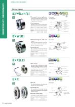
SPRING-ACTUATED BRAKES ELECTROMAGNETIC CLUTCHES & BRAKES Product Lineup Braking use Holding use Dedicated for holding ■ Three types for various applications The line-up includes three types: the L type for braking, the H type for holding, and the S type dedicated for holding. Mountable on either the stator or the plate, allowing the stator (a heat source) to be located freely. Brake type Brake torque Operating temperature Backlash Extremely small size Extremely small size ■ Structure Has release lever Armature Rotor Hexagon head set screw Torque spring Hexagon socket countersunk head bolt Lead...
Open the catalog to page 3
Stable braking Long service life CLUTCHES & BRAKES These reduce annoying high-frequency friction noise during braking. Products that reduce aperiodic noise or armature pull-in noise are also available. ■ Stable braking With low torque fluctuation, these brake loads instantly even when malfunctions occur. Brake torque Operating temperature SPEED CHANGERS & REDUCERS INVERTERS Stud bolt Auxiliary spring LINEAR SHAFT DRIVES Rotor spring Torque spring TORQUE LIMITERS Lead wires Extremely small size High torque ELECTROMAGNETIC-ACTUATED CLUTCHES AND BRAKES ELECTROMAGNETIC CLUTCH & BRAKE UNITS TOOTH...
Open the catalog to page 4
SPRING-ACTUATED BRAKES ELECTROMAGNETIC CLUTCHES & BRAKES Customization Examples ■ Integrated coupling-rotor hub type This is a large version of the BXW with static friction torque of 300 N•m. Backlash is kept extremely small by locking the rotor hub to the rotor via a disc spring. Even more compact devices can be designed by fitting the slim and compact BXR model spline rotor hub into a metal plate-spring-type coupling exterior. ■ Types with Integrated Flanges ■ Special Release Levers Mounting flanges and brake stators can be integrated. This helps reduce the number of components and saves space....
Open the catalog to page 5
I don't see anything with the torque and response I need in your standard products. Can you customize something for me? ETP BUSHINGS ELECTROMAGNETIC CLUTCHES & BRAKES SPEED CHANGERS We can customize units in many ways: outfitting them for overexcitation power supplies or use of inrush current at motor startup, changing the frictional material, boosting torque, increasing response, extending the total energy LINEAR SHAFT DRIVES (service life), suppressing heat generation, and more. Consult Miki Pulley for details. TORQUE LIMITERS ROSTA Yes, we can. For example, we have a long track record creating...
Open the catalog to page 6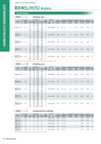
SPRING-ACTUATED BRAKES Coil (at 20℃ ) Static friction torque Voltage Wattage Current Resistance Ts [N·m] [V] [W] [A] [Ω] 12 24 Max. Rotating part Allowable braking Total braking Armature Armature Mass rotation speed moment of inertia energy pull-in time release time energy rate [kg] J [kg·m2] ET[J] ta [s] Pbaℓ [W] tar [s] [min-1] Lead wire UL style Heat resistance class ELECTROMAGNETIC CLUTCHES & BRAKES BXW(L/H/S) Models * Depending on the initial torque characteristics, break-in to condition the engaging surfaces may be required. Coil (at 20℃ ) Static friction torque Voltage Wattage Current...
Open the catalog to page 7
CLUTCHES & BRAKES SPEED CHANGERS Lead wire length: 400 mm Release direction Release direction Lead wire length: 400 mm LINEAR SHAFT DRIVES TORQUE LIMITERS Radial direction dimensions A Axial direction dimensions * There is no release lever option for size #01. * The dimensions in parentheses ( ) are values for BXW- □ - □ S. SERIES ELECTROMAGNETIC-ACTUATED CLUTCHES AND BRAKES ELECTROMAGNETICACTUATED MICRO CLUTCHES & BRAKES ELECTROMAGNETICACTUATED CLUTCHES & BRAKES ELECTROMAGNETIC CLUTCH & BRAKE UNITS SPRING-ACTUATED BRAKE Bore dimensions Bore diameter (dimensional symbol d) Release lever 10: Not...
Open the catalog to page 8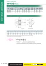
SPRING-ACTUATED BRAKES Specifications Static friction torque Ts [N·m] Coil (at 20℃ ) Voltage Wattage [V] [W] Lead wire Heat resistance class Rotating part moment of inertia J [kg·m2] Allowable braking energy Ebaℓ [J] Total braking energy ET [J] Armature pull-in time ta [s] Armature release time tar [s] * The armature pull-in time and armature release time are taken during DC switching. ELECTROMAGNETIC CLUTCHES & BRAKES BXW(R) Models 30° I Lead wire Length: 200 mm *The lead wire exit for size #01 is located in the dashed area. Radial direction dimensions Axial direction dimensions Bore dimensions...
Open the catalog to page 9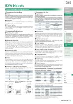
Items Checked for Design Purposes ■ Precautions for Handling Most electromagnetic braking systems are made using flexible materials. Be careful when handling such parts and materials as striking or dropping them or applying excessive force could cause them to become damaged or deformed. This brake is available in braking, holding, and dedicated for holding types according to the application. Do not use BXW(H/R) types for ordinary braking, except for emergency braking in the event of a power outage or the like. You should note that BXW(S) types dedicated for holding cannot effect emergency braking...
Open the catalog to page 10All Miki Pulley Europe AG catalogs and technical brochures
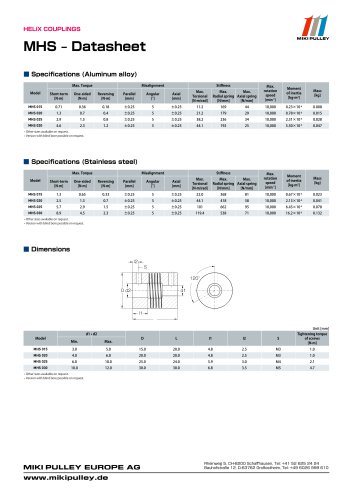 MHS Datasheet
2 Pages
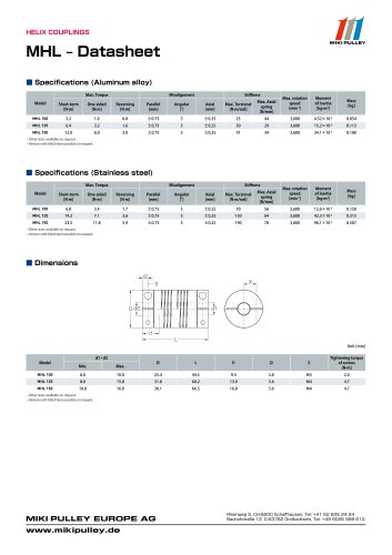 MHL Datasheet
2 Pages
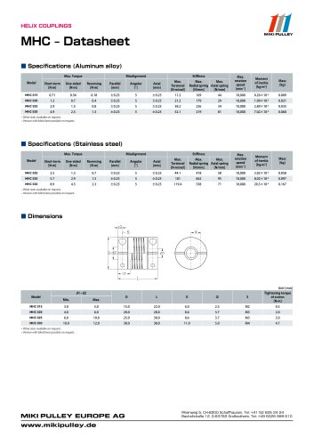 MHC Datasheet
2 Pages
 Precision Springs catalog
12 Pages
 CPG Datasheet
1 Page
 CPG catalog
2 Pages
 Servoflex SFU Catalog
6 Pages
 PSL - D Model
2 Pages
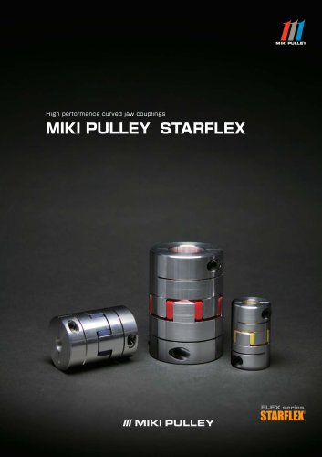 Starflex ALS AN
12 Pages
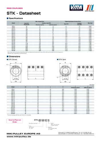 STK Model datasheet
1 Page
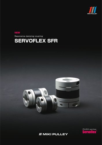 Servoflex SFR Catalog
12 Pages
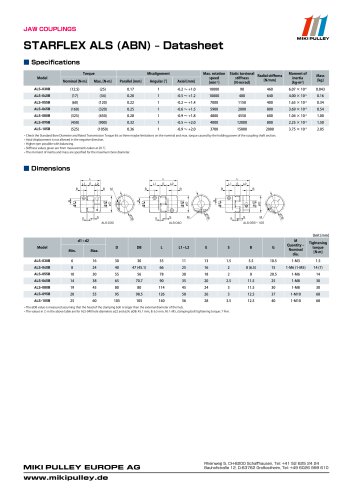 Starflex ALS AN datasheets
9 Pages
 BXR Model datasheet
2 Pages
 BXR-LE Model datasheet
2 Pages
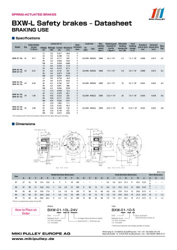 BXW Model datasheets
4 Pages
 SFM Model datasheets
2 Pages
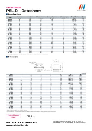 PSL-D series datasheet
2 Pages
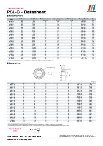 PSL-G series datasheet
2 Pages
 SFC Model Datasheet
10 Pages
 TT(01) Model datasheet
3 Pages
 KSK Model
2 Pages
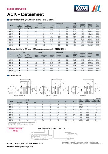 ASK Model datasheet
1 Page
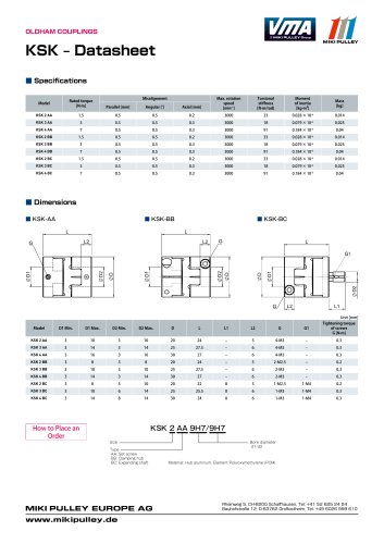 KSK Model datasheet
1 Page
 ASK Model
2 Pages
 STK Catalog
2 Pages
 TT(03) Model datasheet
3 Pages
 BXL-N datasheet
1 Page
 BXL Model datasheet
2 Pages
 BXH Model datasheet
2 Pages
 TT Torque Tender
10 Pages
 SFM Model
8 Pages
 SFS Model
14 Pages
 SFC Model
12 Pages
 PSL - G Model
2 Pages
 Sprflex / Jaw Type
3 Pages
 Paraflex Pin Bush
4 Pages
 Posi Lock / Klemmelemente
18 Pages
 Power Supplies Brakes
26 Pages
 Electromagnetic clutch and brake
14 Pages
 Clutch and Brake Units
50 Pages
 SFF Model
14 Pages
 SFH Model
8 Pages
 DC Motors
12 Pages
 Speed change Pulley
20 Pages
 Baumannflex Models
8 Pages
 Starflex ALS Model
16 Pages
 BXR-LE Model
2 Pages
 BXR Model
4 Pages
 BXW Model
4 Pages
 BXH Model
4 Pages
 BXL Model
4 Pages
 BXL-N Model
2 Pages
 SFF Model datasheets
9 Pages
 SFH Model datasheets
6 Pages
 SFS Model datasheets
21 Pages
 Paraflex CPE, CPU
2 Pages
 CHP Model datasheet
1 Page
 102, 112, CYT datasheets
8 Pages
 121, 122, 125 datasheets
3 Pages
 DMB Model datasheet
1 Page
 SRG Model datasheet
1 Page
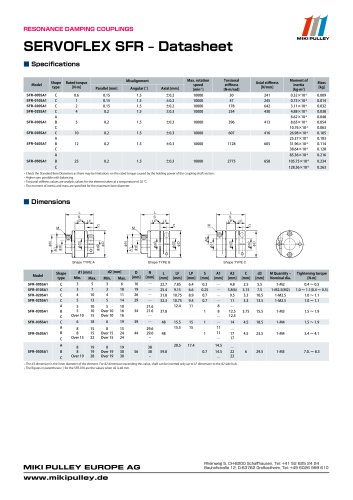
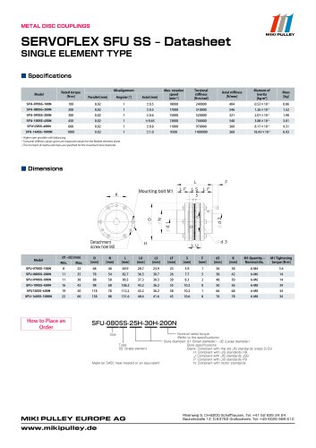


- Clamping device
- MIKI PULLEY flexible coupling
- MIKI PULLEY shaft coupling
- MIKI PULLEY friction brake
- Flange coupling
- Clamping device
- MIKI PULLEY torque coupling
- Rigid coupling
- MIKI PULLEY transmission coupling
- Spring brake
- MIKI PULLEY zero-backlash coupling
- Compression spring
- Sleeve coupling
- MIKI PULLEY compact coupling
- MIKI PULLEY misalignment correction coupling
- MIKI PULLEY motor coupling
- MIKI PULLEY high-torque coupling