- Catalogs
- Miki Pulley Europe AG
- SFH Model
SFH Model
1 /8Pages

SFH Model
1 /8Pages
Catalog excerpts

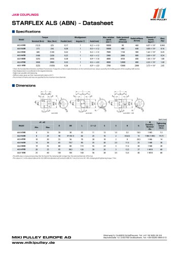
Metal Disc Couplings SFH(S) Types Single Element Type Specification (SFH- □ S) Pilot Bore/Key or Set Screw Misalignment Torsional stiffness [N·m/rad] * Max. rotation speed does not take into account dynamic balance. * The moment of inertia and mass are measured for the maximum bore diameter. Dimensions (SFH- □ S) Pilot Bore/Key or Set Screw F * Pilot bores are to be drilled into the part. See the standard hole-drilling standards of P.86 for information on bore drilling. * The nominal diameter of the reamer bolt is equal to the quantity minus the nominal diameter of the screw threads times the nominal length. Bore diameter: d1 (Small diameter) - d2 (Large diameter) Blank: Pilot bore Type: S Single element Bore specifications Blank : Compliant with the old JIS standards (class 2) E9 H: Compliant with JIS
Open the catalog to page 1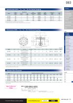
Specification (SFH- □ S- □ K- □ K) Frictional Coupling Torsional stiffness [N·m/rad] SPEED CHANGERS CLUTCHES & BRAKES * Max. rotation speed does not take into account dynamic balance. * The moment of inertia and mass in the table are measured for the maximum bore diameter. LINEAR SHAFT DRIVES TORQUE LIMITERS ROSTA Dimensions (SFH- □ S- □ K- □ K) Frictional Coupling SERIES Metal Disc SERVOFLEX High-rigidity Couplings Link Couplings SCHMIDT Dual Rubber Couplings * The nominal diameters of each bolt and tap are equal to the quantity minus the nominal diameter of the screw threads times the nominal...
Open the catalog to page 2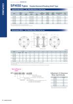
Metal Disc Couplings SFH(G) Types Double Element/Floating Shaft Type Specification (SFH- □ G) Pilot Bore/Key or Set Screw Misalignment Torsional stiffness [N·m/rad] * Max. rotation speed does not take into account dynamic balance. * The moment of inertia and mass are measured for the maximum bore diameter. Dimensions (SFH- □ G) Pilot Bore/Key or Set Screw F * Pilot bores are to be drilled into the part. See the standard hole-drilling standards of P.86 for information on bore drilling. * If you require a product with an LS dimension that exceeds those above, contact Miki Pulley with your required...
Open the catalog to page 3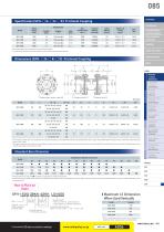
Specification (SFH- □ G- □ K- □ K) Frictional Coupling Torsional stiffness [N·m/rad] SPEED CHANGERS * Max. rotation speed does not take into account dynamic balance. * The moment of inertia and mass in the table are measured for the maximum bore diameter. CLUTCHES & BRAKES INVERTERS LINEAR SHAFT DRIVES TORQUE LIMITERS Dimensions (SFH- □ G- □ K- □ K) Frictional Coupling SERIES Metal Disc Couplings High-rigidity SERVOFLEX Couplings SCHMIDT Dual Rubber 70 SPRFLEX Plastic Bellows Couplings * The bore diameters marked with ● or numbers are supported as standard bore diameter. * Bore diameters whose...
Open the catalog to page 4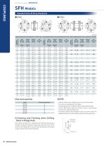
Metal Disc Couplings Standard Hole-Drilling Standards ■ SFH(S) Models compliant with the old JIS standard (class 2) JIS B 1301 1959 Models compliant with the new JIS standard (H9) JIS B 1301 1996 Models compliant with the motor standard JIS C 4210 2001 Keyway height [T1・T2] Nominal bore diameter Nominal bore diameter Nominal bore diameter Bore diameter
Open the catalog to page 5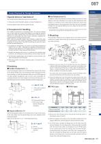
Items Checked for Design Purposes ■ Axial displacement (S) You should note the following to prevent any problems. In addition, restrict the dimension between flange hub faces (S in the (1) Always be careful of parallel, angular, and axial misalignment. diagram) within the allowable error range for axial displacement with CLUTCHES & BRAKES respect to a reference value. Note that the tolerance values were SPEED CHANGERS ■ Special Items to Take Note of (2) Always tighten bolts with the specified torque. calculated based on the assumption that both the level of parallel misalignment and angular deflection...
Open the catalog to page 6
Metal Disc Couplings SFH Models Items Checked for Design Purposes ■ Mounting (3) Pull out three of the pressure bolts loosened in step (2), insert them into detachment screw holes at three locations on the sleeve, and tighten them alternately, a little at a time. The link between the flange hub and shaft will be released. (6) Keep the width of the dimension between flange faces (S dimension in the diagram) within the allowable error range for axial misalignment with respect to the reference value. Note that the tolerance values were calculated based on the assumption that both the level of parallel...
Open the catalog to page 7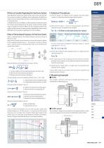
089 ■ Points to Consider Regarding the Feed Screw System Gain adjustment in feed screw systems using a servo motor may cause the (1) Find the torque, Ta, applied to the coupling using the output servo motor to oscillate. If oscillation occurs, adjustment will need to be capacity, P, of the driver and the usage rotation speed, n. made such as by using the filter function or other electrical control system to resolve this issue. To handle issues such as oscillation, it will be necessary to take into account the torsional natural frequency for the system overall during the design stage, including...
Open the catalog to page 8All Miki Pulley Europe AG catalogs and technical brochures
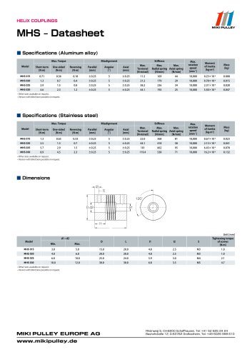 MHS Datasheet
2 Pages
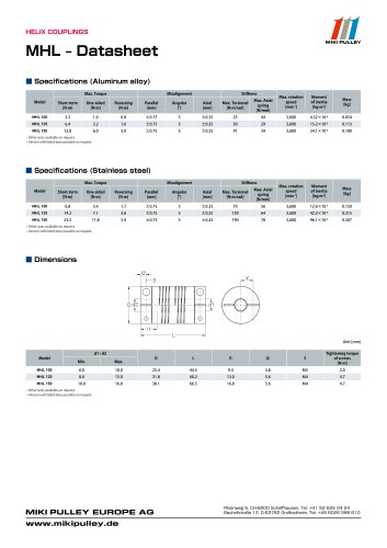 MHL Datasheet
2 Pages
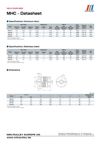 MHC Datasheet
2 Pages
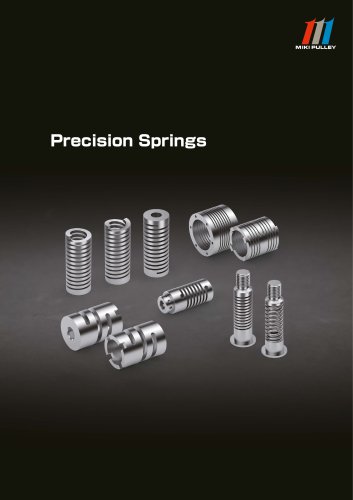 Precision Springs catalog
12 Pages
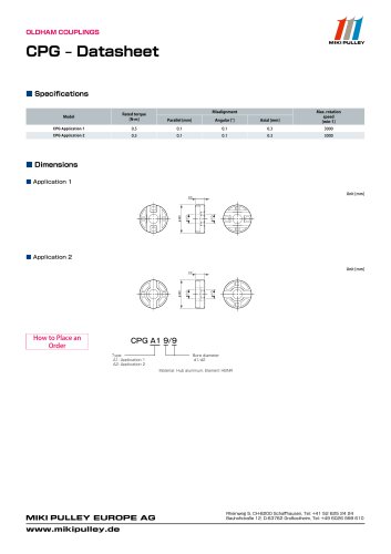 CPG Datasheet
1 Page
 CPG catalog
2 Pages
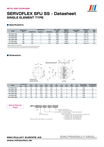
 Servoflex SFU Catalog
6 Pages
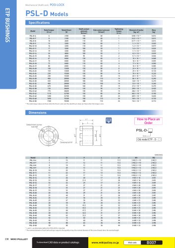 PSL - D Model
2 Pages
 Starflex ALS AN
12 Pages
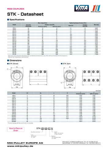 STK Model datasheet
1 Page
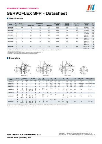
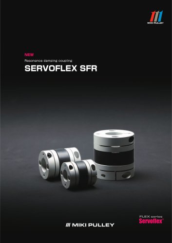 Servoflex SFR Catalog
12 Pages
 Starflex ALS AN datasheets
9 Pages
 BXR Model datasheet
2 Pages
 BXR-LE Model datasheet
2 Pages
 BXW Model datasheets
4 Pages
 SFM Model datasheets
2 Pages
 PSL-D series datasheet
2 Pages
 PSL-G series datasheet
2 Pages
 SFC Model Datasheet
10 Pages
 TT(01) Model datasheet
3 Pages
 KSK Model
2 Pages
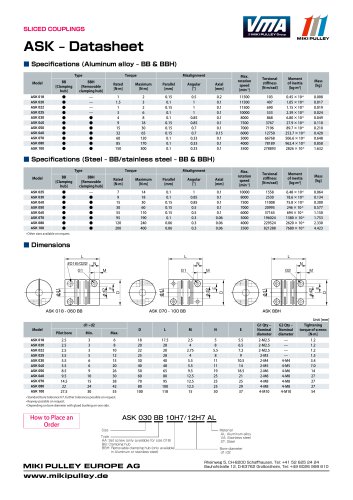 ASK Model datasheet
1 Page
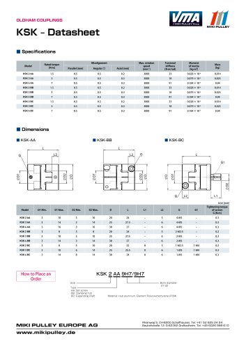 KSK Model datasheet
1 Page
 ASK Model
2 Pages
 STK Catalog
2 Pages
 TT(03) Model datasheet
3 Pages
 BXL-N datasheet
1 Page
 BXL Model datasheet
2 Pages
 BXH Model datasheet
2 Pages
 TT Torque Tender
10 Pages
 SFM Model
8 Pages
 SFS Model
14 Pages
 SFC Model
12 Pages
 PSL - G Model
2 Pages
 Sprflex / Jaw Type
3 Pages
 Paraflex Pin Bush
4 Pages
 Posi Lock / Klemmelemente
18 Pages
 Spring-Actuated Brakes
34 Pages
 Power Supplies Brakes
26 Pages
 Electromagnetic clutch and brake
14 Pages
 Clutch and Brake Units
50 Pages
 SFF Model
14 Pages
 DC Motors
12 Pages
 Speed change Pulley
20 Pages
 Baumannflex Models
8 Pages
 Starflex ALS Model
16 Pages
 BXR-LE Model
2 Pages
 BXR Model
4 Pages
 BXW Model
4 Pages
 BXH Model
4 Pages
 BXL Model
4 Pages
 BXL-N Model
2 Pages
 SFF Model datasheets
9 Pages
 SFH Model datasheets
6 Pages
 SFS Model datasheets
21 Pages
 Paraflex CPE, CPU
2 Pages
 CHP Model datasheet
1 Page
 102, 112, CYT datasheets
8 Pages
 121, 122, 125 datasheets
3 Pages
 DMB Model datasheet
1 Page
 SRG Model datasheet
1 Page


- Clamping device
- MIKI PULLEY flexible coupling
- MIKI PULLEY shaft coupling
- MIKI PULLEY friction brake
- Spring
- Clamping device
- Flange coupling
- MIKI PULLEY torque coupling
- MIKI PULLEY transmission coupling
- Rigid coupling
- Spring brake
- MIKI PULLEY zero-backlash coupling
- Electromagnetic brake
- Compression spring
- Sleeve coupling
- MIKI PULLEY compact coupling
- MIKI PULLEY misalignment correction coupling
- MIKI PULLEY motor coupling
- MIKI PULLEY high-torque coupling