 Website:
Miki Pulley Europe AG
Group: Miki Pulley
Catalog excerpts
ELECTROMAGNETIC-ACTUATED CLUTCHES & BRAKES ELECTROMAGNETIC CLUTCHES & BRAKES ELECTROMAGNETIC-ACTUATED CLUTCHES & BRAKES 1 Printing machinery, bookbinding machinery, food machinery, wrapping machinery, textiles machinery Clutches and Brakes that Accurately Control a Variety of General Industrial Machinery Clutches accurately connect and release power by being located between the driver and the load. Brakes are used to slow or stop load inertia and machinery and to hold things in stationary positions. Using these basic operations and combining clutches and brakes enable a variety of applications such as stepped speed-changing mechanisms, switching between forward and reverse operation, positioning/indexing, and inching. Part of their appeal is the simplicity of control an
Open the catalog to page 1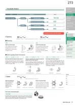
CLUTCHES & BRAKES CLUTCHES & BRAKES Standard type & REDUCERS INVERTERS One-touch mounted type SPEED CHANGERS LINEAR SHAFT DRIVES Standard type One-touch mounted type TORQUE LIMITERS ROSTA CS- -3 Shaft Coupling System (Armature) Shaft Coupling System (Armature) Shaft-mounted type Uses a flange-mounted stator. Designed to be short in the axial direction, requiring less installation space. Uses a bearing-mounted stator. Designed to be relatively easy to mount, reducing the processing and work required for mounting. Directly mounted to the wall Directly mounted to the wall Mounted onto...
Open the catalog to page 2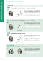
ELECTROMAGNETIC-ACTUATED CLUTCHES & BRAKES ELECTROMAGNETIC CLUTCHES & BRAKES Product Lineup 101 Electromagnetic-actuated Clutches - Flange-mounted Type Stator and rotor are combined and directly mounted on stationary parts, such as frames, and fixed in place. These are short in the axial direction and can make effective use of space near windows. Select the armature according to the coupling type used (through-shaft, butt shaft, etc.). Clutch torque Operating temperature Flange-mounted type CS Electromagnetic-actuated Clutches - Bearing-mounted Type These integrate the stator and rotor,...
Open the catalog to page 3
Types for through-shaft or butt shaft Through-shaft (coupled by winding around parallel shaft) type Butt shaft type ETP BUSHINGS ELECTROMAGNETIC CLUTCHES & BRAKES SPEED CHANGERS & REDUCERS INVERTERS LINEAR SHAFT DRIVES TORQUE LIMITERS Through-shaft (coupled by winding around parallel shaft) type Butt shaft type ELECTROMAGNETIC-ACTUATED CLUTCHES & BRAKES Types for through-shaft or butt shaft ELECTROMAGNETICACTUATED MICRO CLUTCHES & BRAKES ELECTROMAGNETICACTUATED CLUTCHES & BRAKES ELECTROMAGNETIC CLUTCH & BRAKE UNITS SPRING-ACTUATED BRAKE ELECTROMAGNETIC TOOTH CLUTCHES BRAKE MOTORS Types with...
Open the catalog to page 4
ELECTROMAGNETIC-ACTUATED CLUTCHES & BRAKES ELECTROMAGNETIC CLUTCHES & BRAKES Mounting Example Flange-mounting example with 101 Butt shaft mounting example with CS The stator is directly mounted on a stationary part, such as a frame, by a In designs that use butt shafts, the two shafts can be reliably centered mounting flange, and fixed in place. The rotor is linked to the rotation using fitting flanges, as shown in the figure. shaft using a key. The stator and rotor are combined via a narrow air gap that serves as part of the magnetic circuit to form a magnetic pole. Stator Rotor Air gap a...
Open the catalog to page 5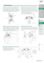
Armature type-3 mounting example with 111 Armature type-2 mounting example on vertical shaft with 111 When armature type-3 is directly mounted on the end face of a V Armature type-2 is a special armature that puts the boss part of the armature CLUTCHES & BRAKES pulley, no armature hub is needed, making for a very efficient design. hub into the space within the stator. That makes it compact. It is short in the These are optimal when space is limited or when a shaft overhangs axial direction even when a pulley or the like is installed on the tip of the brake. SPEED CHANGERS from a wall and...
Open the catalog to page 6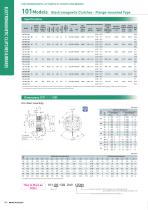
ELECTROMAGNETIC-ACTUATED CLUTCHES AND BRAKES Lead wire Heat resistance class Dynamic Static friction friction torque Td torque Ts [N·m] [N·m] ELECTROMAGNETIC CLUTCHES & BRAKES 101Models Electromagnetic Clutches - Flange-mounted Type Rotating part moment of inertia J Rotor [kg·m2] Total work Torque Torque performed Armature build-up decaying Mass until pull-in time readjustment [kg] time time ta [s] of the air gap td [s] tp [s] ET [J] 0.46 * The dynamic friction torque, Td, is measured at a relative speed of 100 min-1. Depending on the initial torque characteristics, break-in to condition...
Open the catalog to page 7
Shaft bore dimensions Models compliant with JIS standards INVERTERS LINEAR SHAFT DRIVES TORQUE LIMITERS ROSTA * For details on mounting method, see “Items Checked for Design Purposes”. SPEED CHANGERS Armature type-5 keyway standards Dimensional symbol U2, W2: DIN: Compliant with JIS standards P9 Dimensional symbol U1, W1: JIS: Compliant with the old JIS standards (class 2) E9 Size Rotor bore diameter (dimensional symbol d1) Armature bore diameter (dimensional symbol d2) Keyway standards DIN: Compliant with JIS standards P9 JIS: Compliant with the old JIS standards (class 2) E9 SERIES...
Open the catalog to page 8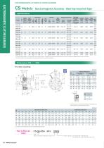
ELECTROMAGNETIC-ACTUATED CLUTCHES & BRAKES Specications Lead wire Dynamic Static friction friction torque torque Td [N·m] Ts [N·m] ELECTROMAGNETIC CLUTCHES & BRAKES CS Models Electromagnetic Clutches - Bearing-mounted Type Heat resistance class Total work performed Armature Torque Torque pull-in until build-up decaying Mass time readjustment time [kg] time ta [s] of the air gap tp [s] td [s] ET [J] Rotating part moment of inertia J * The dynamic friction torque, Td, is measured at a relative speed of 100 min-1. Depending on the initial torque characteristics, break-in to condition the...
Open the catalog to page 9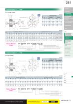
Shaft bore dimensions Size Lead wire length: 400 INVERTERS LINEAR SHAFT DRIVES TORQUE LIMITERS Rotor bore diameter keyway SPEED CHANGERS CLUTCHES & BRAKES Models compliant with the old JIS standards Models compliant with JIS standards Axial direction dimensions * For details on mounting method, see “Items Checked for Design Purposes”. Armature type-5 keyway standards Dimensional symbol U2, W2: DIN: Compliant with JIS standards P9 Dimensional symbol U1, W1: JIS: Compliant with the old JIS standards (class 2) E9 Size Rotor bore diameter (dimensional symbol) Models compliant with JIS standards...
Open the catalog to page 10All Miki Pulley Europe AG catalogs and technical brochures
-
KSK Model
2 Pages
-
ASK Model datasheet
1 Pages
-
ASK Model
2 Pages
-
KSK Model datasheet
1 Pages
-
Starflex ALS AN
12 Pages
-
STK Catalog
2 Pages
-
BXR-LE Model datasheet
2 Pages
-
Servoflex SFR series
4 Pages
-
TT(03) Model datasheet
3 Pages
-
BXL-N datasheet
1 Pages
-
BXW Model datasheets
4 Pages
-
TT Torque Tender
10 Pages
-
SFM Model
8 Pages
-
SFS Model
14 Pages
-
SFC Model
12 Pages
-
PSL - G Model
2 Pages
-
Sprflex / Jaw Type
3 Pages
-
Paraflex Pin Bush
4 Pages
-
Posi Lock / Klemmelemente
18 Pages
-
Spring-Actuated Brakes
34 Pages
-
Power Supplies Brakes
26 Pages
-
Clutch and Brake Units
50 Pages
-
SFF Model
14 Pages
-
SFH Model
8 Pages
-
DC Motors
12 Pages
-
Speed change Pulley
20 Pages
-
Baumannflex Models
8 Pages
-
Starflex ALS Model
16 Pages
-
BXR-LE Model
2 Pages
-
BXR Model
4 Pages
-
BXW Model
4 Pages
-
BXH Model
4 Pages
-
BXL Model
4 Pages
-
BXL-N Model
2 Pages
-
SFF Model datasheets
9 Pages
-
SFH Model datasheets
6 Pages
-
SFM Model datasheets
4 Pages
-
SFS Model datasheets
21 Pages
-
Paraflex CPE, CPU
2 Pages
-
CHP Model datasheet
1 Pages
-
BXR Model datasheet
2 Pages
-
BXH Model datasheet
2 Pages
-
BXL Model datasheet
2 Pages
-
102, 112, CYT datasheets
8 Pages
-
121, 122, 125 datasheets
3 Pages
-
SFC Model Datasheet
6 Pages
-
TT(01) Model datasheet
3 Pages
-
STK Model datasheet
1 Pages
-
DMB Model datasheet
1 Pages
-
SRG Model datasheet
1 Pages


