- Catalogs
- Miki Pulley Europe AG
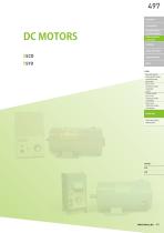
- DC Motors
DC Motors
1 /12Pages

DC Motors
1 /12Pages
Catalog excerpts
ELECTROMAGNETIC CLUTCHES & BRAKES SPEED CHANGERS & REDUCERS INVERTERS LINEAR SHAFT DRIVES TORQUE LIMITERS ROSTA SERIES HOLLOW SHAFT / SOLID SHAFT SPEED CHANGERS AND REDUCERS BELT-TYPE STEPLESS SPEED CHANGER UNITS STAND-ALONE BELT-TYPE STEPLESS SPEED CHANGERS ZERO-MAX (STEPLESS SPEED CHANGERS) DC MOTORS ROTATION SPEED INDICATORS
Open the catalog to page 1
SPEED CHANGERS & REDUCERS SCD High-performance Model with Feedback Control Capability Rated output Power supply voltage Speed change range ■ Stepless Speed Change and Stable Rotation peed can be changed with stable rotation steplessly S across the entire range from a high rated speed of 2500 or 1750 min-1 to a low speed of 1/30 of the rated speed. ■ Safe Protection Function current limiting circuit and fuse prevent overload at A startup and during operation and protect the motor and control board. ■ High Rotation Accuracy constant voltage circuit, load compensation circuit, A and magnetic field...
Open the catalog to page 2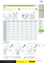
CLUTCHES & BRAKES SPEED CHANGERS LINEAR SHAFT DRIVES TORQUE LIMITERS HOLLOW SHAFT / SOLID SHAFT SPEED CHANGERS AND REDUCERS BELT-TYPE STEPLESS SPEED CHANGER UNITS STAND-ALONE BELT-TYPE STEPLESS SPEED CHANGERS ZERO-MAX (STEPLESS SPEED CHANGERS) DC MOTORS ROTATION SPEED INDICATORS 2- φ30, with rubber bushing Motor SCD-100/100-E Rated output Input voltage Control SCD-100/100-Y board Rated output Input vol
Open the catalog to page 3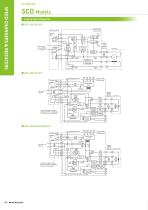
Connection Diagram ■ SCD-100/200-E/Y Control board Operating panel Basic voltage Current limiter Comparator circuit Control panel Rotation speed indicator (Optional) Firing circuit SPEED CHANGERS & REDUCERS Armature voltage Current detector FU2 Magnetic field temperature compensation Control board Control panel Power supply circuit Nmin COMMON Compensation input Rotation speed indicator (Optional) Settings amplifier Startup circuit Current limiter If using with highly frequent startups, ON/OFF is toggled by ③/⑬ with R/V and S/U left ON. Fast-blow fuse Gate circuit Settings amplifier Armature...
Open the catalog to page 4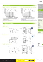
■ SCD-750/1500/2200/3700-E/Y (Drip-Proof Type) Torque [%] ■ SCD-100/200/400-E/Y (Fully-Closed Type) Current limit point Current limit point & REDUCERS INVERTERS CLUTCHES & BRAKES SPEED CHANGERS LINEAR SHAFT DRIVES TORQUE LIMITERS Rotation speed [%] (Rated speed) Rotation speed [%] (Rated speed) The curve in the graph shows the relationship between the load and rotation speed. Δ N shows a speed change when the load is changed from 0 to 100%. The speed under 150% load is 0. The shaded area shows the continuous operating range. Continuous operation is possible within the speed change range with...
Open the catalog to page 5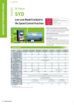
SPEED CHANGERS & REDUCERS SYD Low-cost Model Limited to the Speed Control Function Rated output Power supply voltage Speed change range ■ Stepless Speed Change and Stable Rotation peed can be changed with stable rotation steplessly S across the entire range from a high rated speed of 2500 min-1 to a low speed of 1/20 of the rated speed. ■ Safe Protection Function current limiting circuit and fuse prevent overload at A startup and during operation and protect the motor and control board. ■ High Rotation Accuracy constant voltage circuit, load compensation circuit, A and magnetic field temperature...
Open the catalog to page 6
CLUTCHES & BRAKES SPEED CHANGERS LINEAR SHAFT DRIVES TORQUE LIMITERS HOLLOW SHAFT / SOLID SHAFT SPEED CHANGERS AND REDUCERS BELT-TYPE STEPLESS SPEED CHANGER UNITS STAND-ALONE BELT-TYPE STEPLESS SPEED CHANGERS ZERO-MAX (STEPLESS SPEED CHANGERS) ROTATION SPEED INDICATORS Motor SYD-100/100-E Rated output Input voltage Control SYD-100/100-Y board Rated output Type Y-type: Y; P-type: P Input voltage
Open the catalog to page 7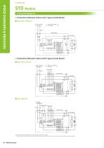
Connection Diagram ■ Connection between motor and Y-type control board ■ SYD-100 to 1500-E/Y Control board Control power supply Gate circuit Feedback circuit Magnetic field compensation circuit Speed setter Comparator circuit SPEED CHANGERS & REDUCERS Current limiter circuit Armature current detector circuit Magnetic field current detector circuit ■ Connection between motor and P-type control board ■ SYD-100 to 750-E/P Control board Control power supply Gate circuit Comparator circuit Feedback circuit Magnetic field compensation circuit IR compensation circuit Current limiter circuit Armature...
Open the catalog to page 8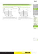
Current limit point Rated torque The following figures show the characteristics and continuous operating range of DC motors. Current limit point Rated torque SPEED CHANGERS & REDUCERS INVERTERS CLUTCHES & BRAKES LINEAR SHAFT DRIVES TORQUE LIMITERS ROSTA * The curve in the graph shows the relationship between the load and rotation speed. Δ N shows a speed change when the load is changed from 0 to 100%. The speed under 150% load is 0. * The shaded area shows the continuous operating range. Continuous operation is possible within the speed change range with 100% torque (rated torque). The curve...
Open the catalog to page 9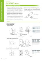
SPEED CHANGERS & REDUCERS SCD/SYD Models Items Checked for Design Purposes 1. Temperature rise: Motors of up to 750 W have Class B insulation a n d m o t o r s o f 1.5 k W o r m o r e h a v e C l a s s F i n s u l a t i o n . Accordingly, the temperature rise limit of the armature winding is 90℃ and 110℃ . If the load is appropriate, the temperature of the outer frame is usually about 15℃ to 25℃ lower than the temperature of the winding. Therefore, it is so hot that you cannot touch it for a long time. However, you may continue operation if the temperature does not exceed the above value. in...
Open the catalog to page 10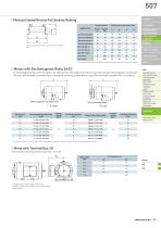
507 ■ Vitreous Enamel Resistor for Dynamic Braking COUPLINGS Standard braking Applied motor Braking resistor dimensions [mm] ■ Motors with Electromagnetic Brake, EA/EC (EA type, where the brake is activated when it is energized) and spring-actuated type (EC type, where the brake is released when it is energized). Electromagnetic-actuated brake TORQUE LIMITERS ROSTA HOLLOW SHAFT / SOLID SHAFT SPEED CHANGERS AND REDUCERS BELT-TYPE STEPLESS SPEED CHANGER UNITS STAND-ALONE BELT-TYPE STEPLESS SPEED CHANGERS ZERO-MAX (STEPLESS SPEED CHANGERS) Spring-actuated brake LINEAR SHAFT DRIVES n electromagnetic...
Open the catalog to page 11All Miki Pulley Europe AG catalogs and technical brochures
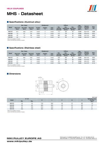 MHS Datasheet
2 Pages
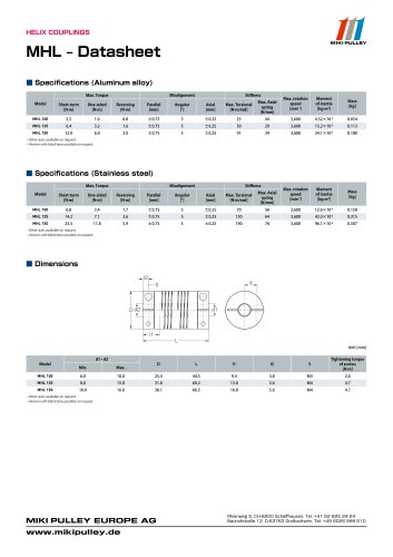 MHL Datasheet
2 Pages
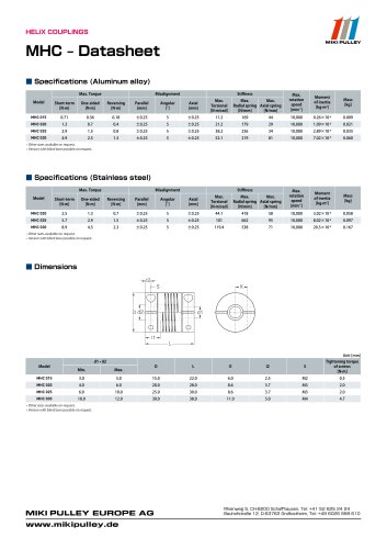 MHC Datasheet
2 Pages
 Precision Springs catalog
12 Pages
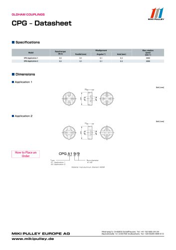 CPG Datasheet
1 Page
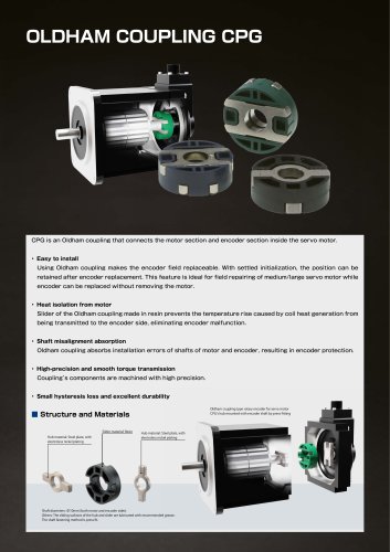 CPG catalog
2 Pages
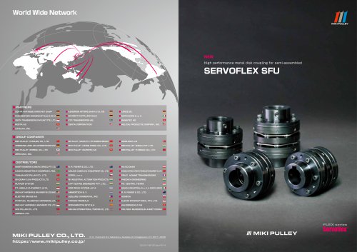 Servoflex SFU Catalog
6 Pages
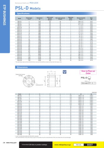 PSL - D Model
2 Pages
 Starflex ALS AN
12 Pages
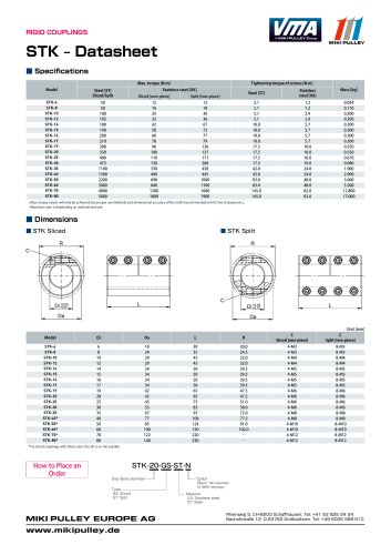 STK Model datasheet
1 Page
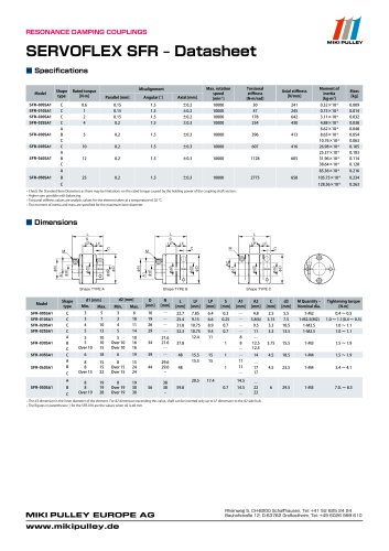
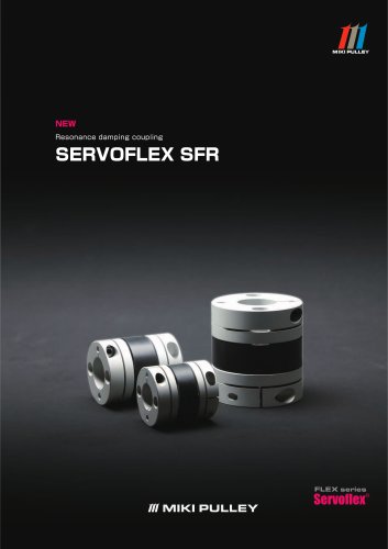 Servoflex SFR Catalog
12 Pages
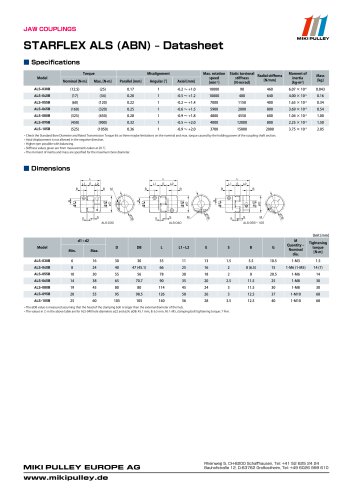 Starflex ALS AN datasheets
9 Pages
 BXR Model datasheet
2 Pages
 BXR-LE Model datasheet
2 Pages
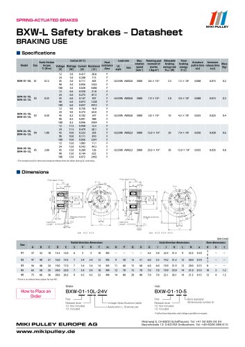 BXW Model datasheets
4 Pages
 SFM Model datasheets
2 Pages
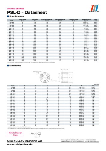 PSL-D series datasheet
2 Pages
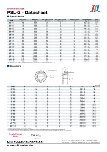 PSL-G series datasheet
2 Pages
 SFC Model Datasheet
10 Pages
 TT(01) Model datasheet
3 Pages
 KSK Model
2 Pages
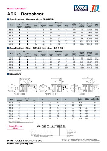 ASK Model datasheet
1 Page
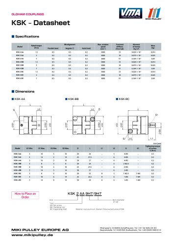 KSK Model datasheet
1 Page
 ASK Model
2 Pages
 STK Catalog
2 Pages
 TT(03) Model datasheet
3 Pages
 BXL-N datasheet
1 Page
 BXL Model datasheet
2 Pages
 BXH Model datasheet
2 Pages
 TT Torque Tender
10 Pages
 SFM Model
8 Pages
 SFS Model
14 Pages
 SFC Model
12 Pages
 PSL - G Model
2 Pages
 Sprflex / Jaw Type
3 Pages
 Paraflex Pin Bush
4 Pages
 Posi Lock / Klemmelemente
18 Pages
 Spring-Actuated Brakes
34 Pages
 Power Supplies Brakes
26 Pages
 Electromagnetic clutch and brake
14 Pages
 Clutch and Brake Units
50 Pages
 SFF Model
14 Pages
 SFH Model
8 Pages
 Speed change Pulley
20 Pages
 Baumannflex Models
8 Pages
 Starflex ALS Model
16 Pages
 BXR-LE Model
2 Pages
 BXR Model
4 Pages
 BXW Model
4 Pages
 BXH Model
4 Pages
 BXL Model
4 Pages
 BXL-N Model
2 Pages
 SFF Model datasheets
9 Pages
 SFH Model datasheets
6 Pages
 SFS Model datasheets
21 Pages
 Paraflex CPE, CPU
2 Pages
 CHP Model datasheet
1 Page
 102, 112, CYT datasheets
8 Pages
 121, 122, 125 datasheets
3 Pages
 DMB Model datasheet
1 Page
 SRG Model datasheet
1 Page


- Clamping device
- MIKI PULLEY flexible coupling
- MIKI PULLEY shaft coupling
- MIKI PULLEY friction brake
- Clamping device
- Flange coupling
- MIKI PULLEY torque coupling
- MIKI PULLEY transmission coupling
- Rigid coupling
- Spring brake
- MIKI PULLEY zero-backlash coupling
- Compression spring
- Sleeve coupling
- MIKI PULLEY compact coupling
- MIKI PULLEY misalignment correction coupling
- MIKI PULLEY motor coupling
- MIKI PULLEY high-torque coupling