- Catalogs
- Miki Pulley Europe AG
- BXW Model
BXW Model
1 /4Pages

BXW Model
1 /4Pages
Catalog excerpts
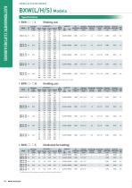
SPRING-ACTUATED BRAKES Coil (at 20℃ ) Static friction torque Voltage Wattage Current Resistance Ts [N·m] [V] [W] [A] [Ω] 12 24 Max. Rotating part Allowable braking Total braking Armature Armature Mass rotation speed moment of inertia energy pull-in time release time energy rate [kg] J [kg·m2] ET[J] ta [s] Pbaℓ [W] tar [s] [min-1] Lead wire UL style Heat resistance class ELECTROMAGNETIC CLUTCHES & BRAKES BXW(L/H/S) Models * Depending on the initial torque characteristics, break-in to condition the engaging surfaces may be required. Coil (at 20℃ ) Static friction torque Voltage Wattage Current Resistance Ts [N·m] [V] [W] [A] [Ω] Lead wire UL style Armature Max. Rotating part Allowable braking Total braking Armature Mass energy rate rotation speed moment of inertia energy pull-in time release time [kg] Pbaℓ [W] tar [s] [min-1] J [kg·m2] ET[J] ta [s] Coil (at 20℃ ) Static friction torque Voltage Wattage Current Resistance Ts [N·m] [A] [V] [W] [Ω] Heat resistance class Heat resistance class Lead wire UL style Armature Max. Rotating part Allowable braking Total braking Armature Mass energy rate rotation speed moment of inertia energy pull-in time release time [kg] -1 2 Pbaℓ [W] tar [s] [min ] J [kg·m ] ET[J] ta [s]
Open the catalog to page 1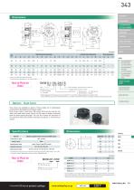
CLUTCHES & BRAKES SPEED CHANGERS Lead wire length: 400 mm Release direction Release direction Lead wire length: 400 mm LINEAR SHAFT DRIVES TORQUE LIMITERS Radial direction dimensions A Axial direction dimensions * There is no release lever option for size #01. * The dimensions in parentheses ( ) are values for BXW- □ - □ S. SERIES ELECTROMAGNETIC-ACTUATED CLUTCHES AND BRAKES ELECTROMAGNETICACTUATED MICRO CLUTCHES & BRAKES ELECTROMAGNETICACTUATED CLUTCHES & BRAKES ELECTROMAGNETIC CLUTCH & BRAKE UNITS SPRING-ACTUATED BRAKE Bore dimensions Bore diameter (dimensional symbol d) Release lever 10: Not...
Open the catalog to page 2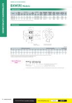
SPRING-ACTUATED BRAKES Specifications Static friction torque Ts [N·m] Coil (at 20℃ ) Voltage Wattage [V] [W] Lead wire Heat resistance class Rotating part moment of inertia J [kg·m2] Allowable braking energy Ebaℓ [J] Total braking energy ET [J] Armature pull-in time ta [s] Armature release time tar [s] * The armature pull-in time and armature release time are taken during DC switching. ELECTROMAGNETIC CLUTCHES & BRAKES BXW(R) Models 30° I Lead wire Length: 200 mm *The lead wire exit for size #01 is located in the dashed area. Radial direction dimensions Axial direction dimensions Bore dimensions...
Open the catalog to page 3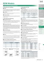
Items Checked for Design Purposes ■ Precautions for Handling Most electromagnetic braking systems are made using flexible materials. Be careful when handling such parts and materials as striking or dropping them or applying excessive force could cause them to become damaged or deformed. This brake is available in braking, holding, and dedicated for holding types according to the application. Do not use BXW(H/R) types for ordinary braking, except for emergency braking in the event of a power outage or the like. You should note that BXW(S) types dedicated for holding cannot effect emergency braking...
Open the catalog to page 4All Miki Pulley Europe AG catalogs and technical brochures
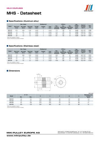 MHS Datasheet
2 Pages
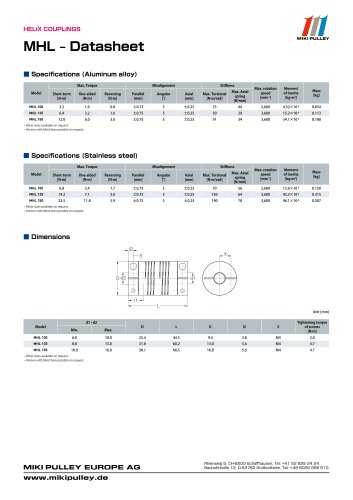 MHL Datasheet
2 Pages
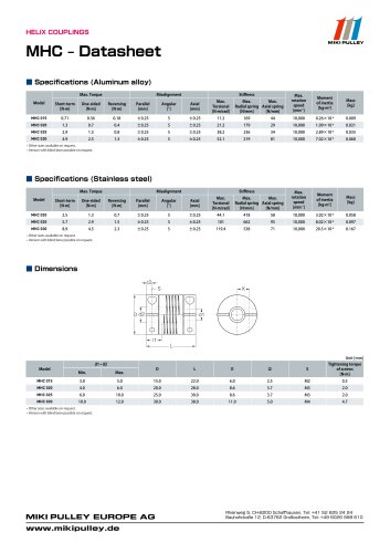 MHC Datasheet
2 Pages
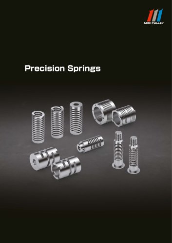 Precision Springs catalog
12 Pages
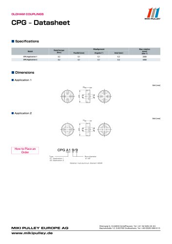 CPG Datasheet
1 Page
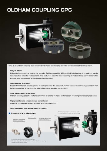 CPG catalog
2 Pages
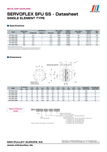
 Servoflex SFU Catalog
6 Pages
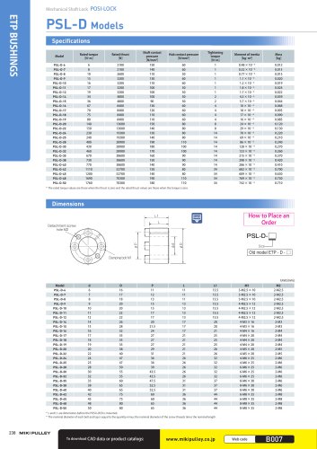 PSL - D Model
2 Pages
 Starflex ALS AN
12 Pages
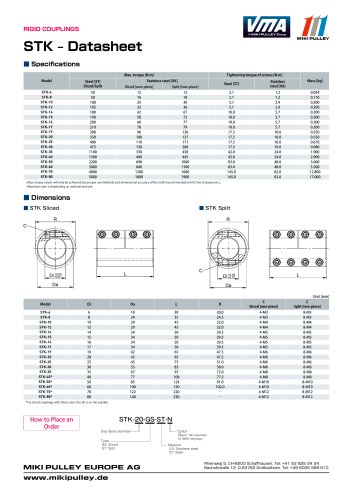 STK Model datasheet
1 Page
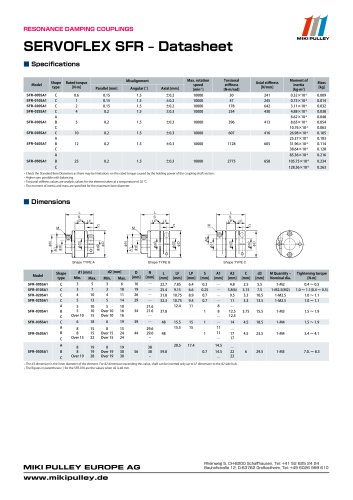
 Servoflex SFR Catalog
12 Pages
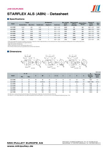 Starflex ALS AN datasheets
9 Pages
 BXR Model datasheet
2 Pages
 BXR-LE Model datasheet
2 Pages
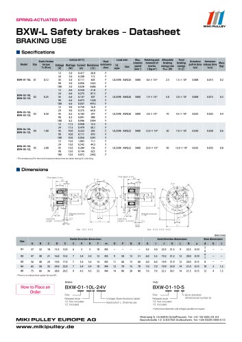 BXW Model datasheets
4 Pages
 SFM Model datasheets
2 Pages
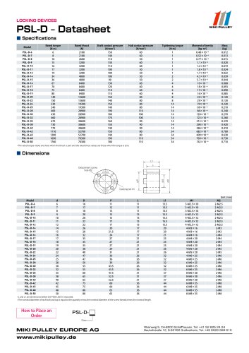 PSL-D series datasheet
2 Pages
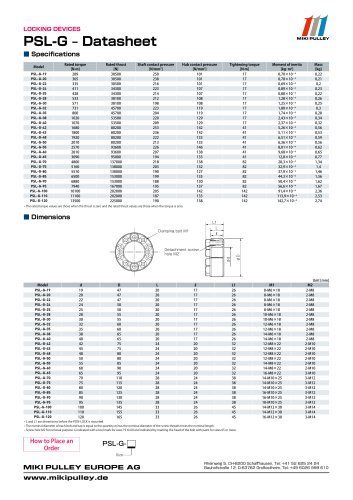 PSL-G series datasheet
2 Pages
 SFC Model Datasheet
10 Pages
 TT(01) Model datasheet
3 Pages
 KSK Model
2 Pages
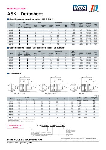 ASK Model datasheet
1 Page
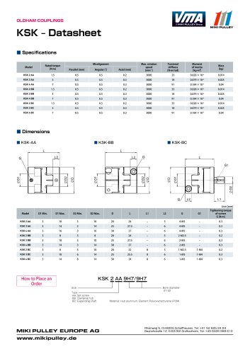 KSK Model datasheet
1 Page
 ASK Model
2 Pages
 STK Catalog
2 Pages
 TT(03) Model datasheet
3 Pages
 BXL-N datasheet
1 Page
 BXL Model datasheet
2 Pages
 BXH Model datasheet
2 Pages
 TT Torque Tender
10 Pages
 SFM Model
8 Pages
 SFS Model
14 Pages
 SFC Model
12 Pages
 PSL - G Model
2 Pages
 Sprflex / Jaw Type
3 Pages
 Paraflex Pin Bush
4 Pages
 Posi Lock / Klemmelemente
18 Pages
 Spring-Actuated Brakes
34 Pages
 Power Supplies Brakes
26 Pages
 Electromagnetic clutch and brake
14 Pages
 Clutch and Brake Units
50 Pages
 SFF Model
14 Pages
 SFH Model
8 Pages
 DC Motors
12 Pages
 Speed change Pulley
20 Pages
 Baumannflex Models
8 Pages
 Starflex ALS Model
16 Pages
 BXR-LE Model
2 Pages
 BXR Model
4 Pages
 BXH Model
4 Pages
 BXL Model
4 Pages
 BXL-N Model
2 Pages
 SFF Model datasheets
9 Pages
 SFH Model datasheets
6 Pages
 SFS Model datasheets
21 Pages
 Paraflex CPE, CPU
2 Pages
 CHP Model datasheet
1 Page
 102, 112, CYT datasheets
8 Pages
 121, 122, 125 datasheets
3 Pages
 DMB Model datasheet
1 Page
 SRG Model datasheet
1 Page


- Clamping device
- MIKI PULLEY flexible coupling
- MIKI PULLEY shaft coupling
- MIKI PULLEY friction brake
- Clamping device
- Flange coupling
- MIKI PULLEY torque coupling
- MIKI PULLEY transmission coupling
- Rigid coupling
- Spring brake
- MIKI PULLEY zero-backlash coupling
- Electromagnetic brake
- Compression spring
- Sleeve coupling
- MIKI PULLEY compact coupling
- MIKI PULLEY misalignment correction coupling
- MIKI PULLEY motor coupling
- MIKI PULLEY high-torque coupling