- Catalogs
- Miki Pulley Europe AG
- BXR-LE Model
BXR-LE Model
1 /2Pages

BXR-LE Model
1 /2Pages
Catalog excerpts
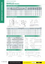
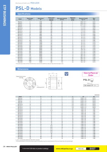
SPRING-ACTUATED BRAKES Specifications (Brake unit) Size Lead wire Coil (at 20℃ ) Static Overexcitation output Normal excitation output Heat friction resistance torque class Ts [N·m] Voltage Wattage Current Resistance Voltage Wattage Current Resistance [V] [W] [A] [Ω] [V] [W] [A] [Ω] Armature Armature Max. Rotating part Allowable Total pull-in release rotation moment of braking braking Mass time time speed energy energy inertia [kg] (24 V DC) (7 V DC) [min-1] J [kg·m2] Ebaℓ [J] ET [J] ta [s] tar [s] Dimensions (Brake unit) (K) a Rotor hub machining dimensions * The rotor hub used to couple the shaft and rotor can either be provided by the customer based on the above diagram or selected from the optional products on the right-hand page. Rotor hubs can also be recommended or fabricated to the desired shape. Consult Miki Pulley for details. Rotor hub recommended mounting position: H φAh9 (centering mark depth: 5 mm) ELECTROMAGNETIC CLUTCHES & BRAKES BXR(LE) Models Lead wire length: 400 mm Unit [mm] Axial direction dimensions Rotor hub machining dimensions Radial direction dimensions A Specifications (Controller) Model 1000 V AC, 50/60 Hz, 1 min. (input/output - between terminal and case) Ambient environment Dielectric strength voltage Input −) Connects the 24 V DC smoothing power supply (-) ( Connects the spring-actuated brake (either pole) Connects the spring-actuated brake (either pole) Lead wire (Blue) *Controlled using ON/OFF on input side. Output Blue - Blue *Case PBT (UL94V-0), Mold: Epoxy (UL94V-0) : Brake coil Lead wire (Blue) Control circuit 24V DC smoothing power supply Lead wire (Black) Timing Chart (Controller) Structure (Controller) Input +) Connects the 24 V DC smoothing power supply (+) ( Lead wire 500 V DC, 100 M Ω with Megger (input/output - between terminal and case) Insulating resistance 1.0 A DC (ambient temp.: 20° 0.8 A DC (ambient temp.: 60° C), C) Time rating 24V DC ± 10% smoothing power supply Initial: 24 V DC (0.2 sec.) Constant: 7 V DC ( ± 10%), PWM control * When the input voltage is 21 V DC, the output volta
Open the catalog to page 1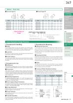
Options Rotor Hub ■ Set screw type (C) SPEED CHANGERS TORQUE LIMITERS ELECTROMAGNETIC-ACTUATED CLUTCHES AND BRAKES LINEAR SHAFT DRIVES CLUTCHES & BRAKES Bore diameter (dimension symbol: d) Size Controller set type Option (Rotor Hub) Blank: No rotor hub C: Set screw type Nominal static friction torque P: Press fit type (3-digit number listed in the specifications tables) Items Checked for Design Purposes ELECTROMAGNETICACTUATED MICRO CLUTCHES & BRAKES ELECTROMAGNETICACTUATED CLUTCHES & BRAKES ELECTROMAGNETIC CLUTCH & BRAKE UNITS SPRING-ACTUATED BRAKE Electromagnetic brakes use many soft materials....
Open the catalog to page 2All Miki Pulley Europe AG catalogs and technical brochures
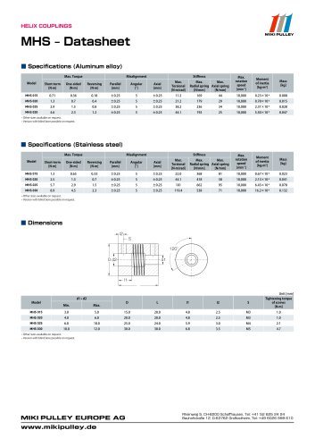 MHS Datasheet
2 Pages
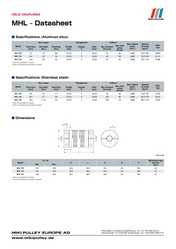 MHL Datasheet
2 Pages
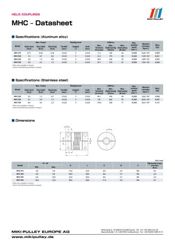 MHC Datasheet
2 Pages
 Precision Springs catalog
12 Pages
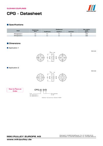 CPG Datasheet
1 Page
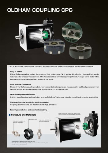 CPG catalog
2 Pages
 Servoflex SFU Catalog
6 Pages
 PSL - D Model
2 Pages
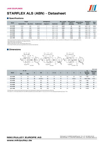
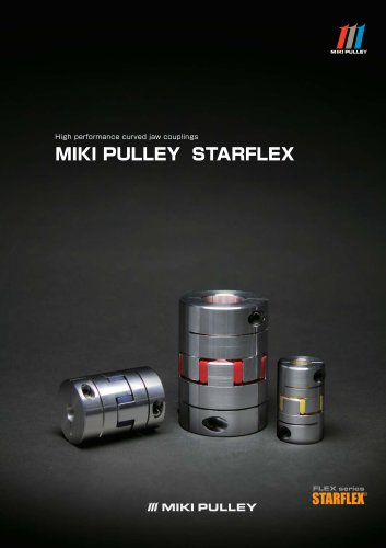 Starflex ALS AN
12 Pages
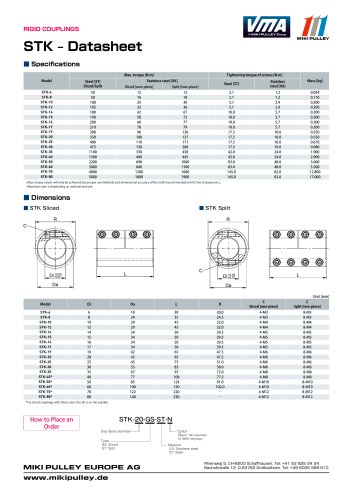 STK Model datasheet
1 Page
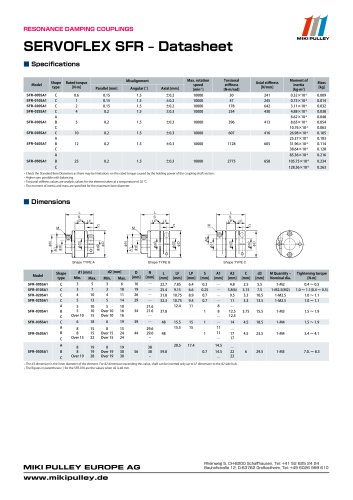
 Servoflex SFR Catalog
12 Pages
 Starflex ALS AN datasheets
9 Pages
 BXR Model datasheet
2 Pages
 BXR-LE Model datasheet
2 Pages
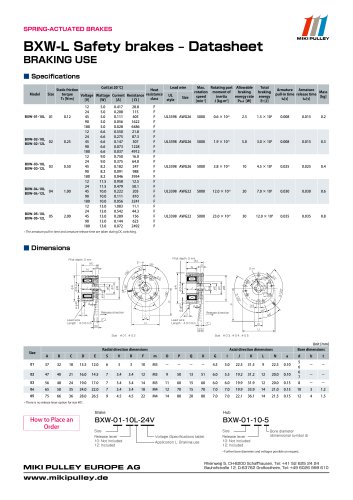 BXW Model datasheets
4 Pages
 SFM Model datasheets
2 Pages
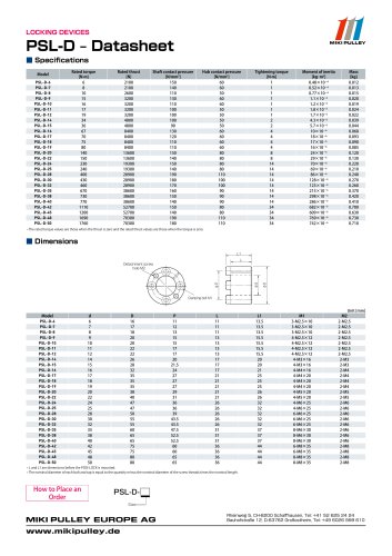 PSL-D series datasheet
2 Pages
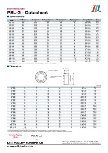 PSL-G series datasheet
2 Pages
 SFC Model Datasheet
10 Pages
 TT(01) Model datasheet
3 Pages
 KSK Model
2 Pages
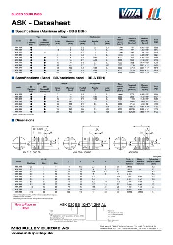 ASK Model datasheet
1 Page
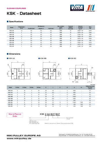 KSK Model datasheet
1 Page
 ASK Model
2 Pages
 STK Catalog
2 Pages
 TT(03) Model datasheet
3 Pages
 BXL-N datasheet
1 Page
 BXL Model datasheet
2 Pages
 BXH Model datasheet
2 Pages
 TT Torque Tender
10 Pages
 SFM Model
8 Pages
 SFS Model
14 Pages
 SFC Model
12 Pages
 PSL - G Model
2 Pages
 Sprflex / Jaw Type
3 Pages
 Paraflex Pin Bush
4 Pages
 Posi Lock / Klemmelemente
18 Pages
 Spring-Actuated Brakes
34 Pages
 Power Supplies Brakes
26 Pages
 Electromagnetic clutch and brake
14 Pages
 Clutch and Brake Units
50 Pages
 SFF Model
14 Pages
 SFH Model
8 Pages
 DC Motors
12 Pages
 Speed change Pulley
20 Pages
 Baumannflex Models
8 Pages
 Starflex ALS Model
16 Pages
 BXR Model
4 Pages
 BXW Model
4 Pages
 BXH Model
4 Pages
 BXL Model
4 Pages
 BXL-N Model
2 Pages
 SFF Model datasheets
9 Pages
 SFH Model datasheets
6 Pages
 SFS Model datasheets
21 Pages
 Paraflex CPE, CPU
2 Pages
 CHP Model datasheet
1 Page
 102, 112, CYT datasheets
8 Pages
 121, 122, 125 datasheets
3 Pages
 DMB Model datasheet
1 Page
 SRG Model datasheet
1 Page


- Clamping device
- MIKI PULLEY flexible coupling
- MIKI PULLEY shaft coupling
- MIKI PULLEY friction brake
- Clamping device
- Flange coupling
- MIKI PULLEY torque coupling
- Rigid coupling
- MIKI PULLEY transmission coupling
- MIKI PULLEY zero-backlash coupling
- Spring brake
- Compression spring
- Sleeve coupling
- MIKI PULLEY compact coupling
- MIKI PULLEY misalignment correction coupling
- MIKI PULLEY motor coupling
- MIKI PULLEY high-torque coupling