- Catalogs
- Miki Pulley Europe AG
- BXH Model datasheet
BXH Model datasheet
1 /2Pages

BXH Model datasheet
1 /2Pages
Catalog excerpts

SPRING-ACTUATED BRAKES BXH Safety brakes – Datasheet ■ Specifications Static friction torque TS [N·m] Coil [at 20 ℃] Lead wire Heat Voltage Wattage Current Resistance resistance UL style Size class [V] [W] [A] [Ω] DC24 Armature Armature Mass pull-in time release time [kg] ta [s] tar [s] Total braking energy ET [J] Max. Rotating part Allowable rotation moment of braking speed inertia energy rate [min-1] J [kg·m2] Ebaℓ [J] • The armature pull-in time and armature release time are taken during DC switching. Lead wire length: 400 mm Bore diameter (dimensional symbol d) Option number 10: Standard Voltage (Specifications table) • Further bore diameters and voltages possible on request.
Open the catalog to page 1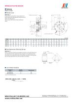
SPRING-ACTUATED BRAKES ■ Options Made to Order ■ Release Lever Option No.: 12 We also offer an option with a manual release lever. See the dimensions table below for the dimensions of brakes with release levers. Please contact Miki Pulley for other specification values. Release lever position U Lead wire length: 400 ■ Quiet Mechanism (Silencing Spring) Option No.: S1 There is a extremely small structural backlash (see figure on the right) between the rotor and the rotor hub. In applications that are prone to microvibrations of the drive shaft such as single-phase motors, this backlash may produce...
Open the catalog to page 2All Miki Pulley Europe AG catalogs and technical brochures
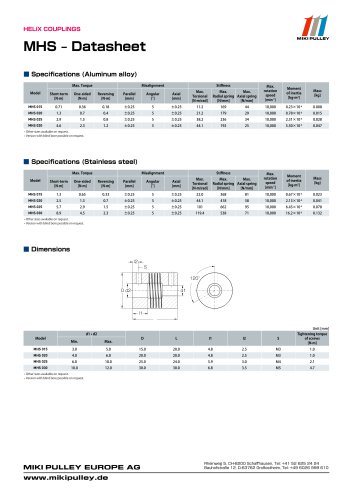 MHS Datasheet
2 Pages
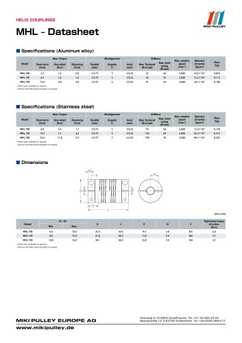 MHL Datasheet
2 Pages
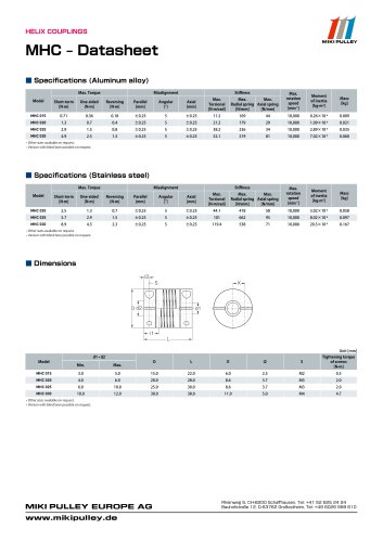 MHC Datasheet
2 Pages
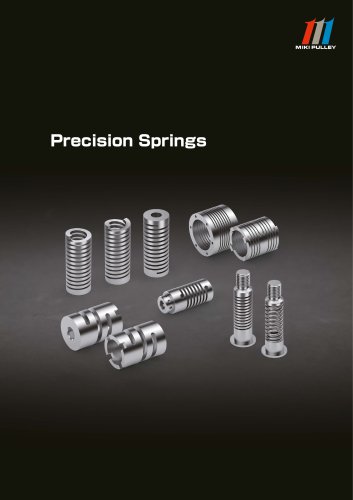 Precision Springs catalog
12 Pages
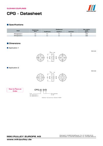 CPG Datasheet
1 Page
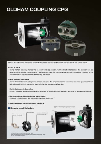 CPG catalog
2 Pages
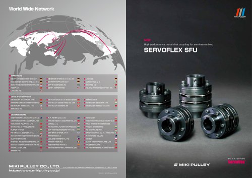 Servoflex SFU Catalog
6 Pages
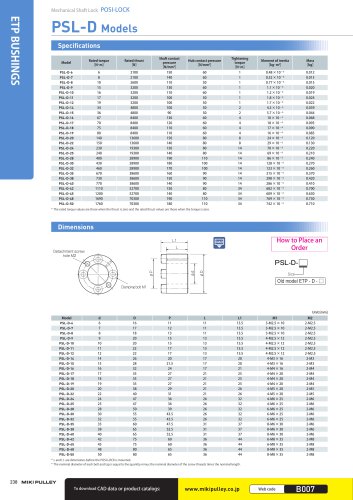 PSL - D Model
2 Pages
 Starflex ALS AN
12 Pages
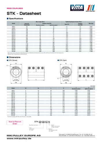 STK Model datasheet
1 Page
 Servoflex SFR Catalog
12 Pages
 Starflex ALS AN datasheets
9 Pages
 BXR Model datasheet
2 Pages
 BXR-LE Model datasheet
2 Pages
 BXW Model datasheets
4 Pages
 SFM Model datasheets
2 Pages
 PSL-D series datasheet
2 Pages
 PSL-G series datasheet
2 Pages
 SFC Model Datasheet
10 Pages
 TT(01) Model datasheet
3 Pages
 KSK Model
2 Pages
 ASK Model datasheet
1 Page
 KSK Model datasheet
1 Page
 ASK Model
2 Pages
 STK Catalog
2 Pages
 TT(03) Model datasheet
3 Pages
 BXL-N datasheet
1 Page
 BXL Model datasheet
2 Pages
 TT Torque Tender
10 Pages
 SFM Model
8 Pages
 SFS Model
14 Pages
 SFC Model
12 Pages
 PSL - G Model
2 Pages
 Sprflex / Jaw Type
3 Pages
 Paraflex Pin Bush
4 Pages
 Posi Lock / Klemmelemente
18 Pages
 Spring-Actuated Brakes
34 Pages
 Power Supplies Brakes
26 Pages
 Electromagnetic clutch and brake
14 Pages
 Clutch and Brake Units
50 Pages
 SFF Model
14 Pages
 SFH Model
8 Pages
 DC Motors
12 Pages
 Speed change Pulley
20 Pages
 Baumannflex Models
8 Pages
 Starflex ALS Model
16 Pages
 BXR-LE Model
2 Pages
 BXR Model
4 Pages
 BXW Model
4 Pages
 BXH Model
4 Pages
 BXL Model
4 Pages
 BXL-N Model
2 Pages
 SFF Model datasheets
9 Pages
 SFH Model datasheets
6 Pages
 SFS Model datasheets
21 Pages
 Paraflex CPE, CPU
2 Pages
 CHP Model datasheet
1 Page
 102, 112, CYT datasheets
8 Pages
 121, 122, 125 datasheets
3 Pages
 DMB Model datasheet
1 Page
 SRG Model datasheet
1 Page


- Clamping device
- MIKI PULLEY flexible coupling
- MIKI PULLEY shaft coupling
- MIKI PULLEY friction brake
- Clamping device
- Flange coupling
- MIKI PULLEY torque coupling
- Rigid coupling
- MIKI PULLEY transmission coupling
- MIKI PULLEY zero-backlash coupling
- Spring brake
- Electromagnetic brake
- Compression spring
- Sleeve coupling
- MIKI PULLEY compact coupling
- Overload clutch
- MIKI PULLEY misalignment correction coupling
- MIKI PULLEY motor coupling
- MIKI PULLEY high-torque coupling