
Catalog excerpts
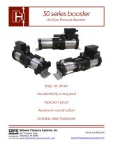
50 series booster Air/Gas Pressure Booster Shop air driven No electricity is required Explosion proof Aluminum construction MPS Midwest Pressure Systems, Inc. 850 Transport Drive M I DWEST PRESSURE SY S T E M S Stainless steel hardware
Open the catalog to page 1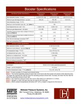
Booster Specifications Gas Boost Cylinder Specifications Bore diameter & stroke - in (mm) Maximum gas discharge pressure - psi (bar) Maximum recommended cycle rate - cpm (Note 1) Gas displacement per cycle - cf (l) Operating pressure boost ratio (multiple of drive air pressure) (Note 2) Maximum pressure boost ratio (multiple of drive air pressure) (Note 3) Gas inlet and discharge connection FNPT Seal vent connections FNPT Air Drive Cylinder Specifications Bore diameter & stroke - in (mm) Maximum drive pressure - psi (bar) (Note 4) Drive air inlet connections FNPT Drive air exhaust...
Open the catalog to page 2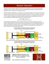
Booster Operation The piston in the drive cylinder is attached to the piston in the boost cylinder. As the drive piston reciprocates, it compresses the gas in the boost cylinder. Please visit www.midwestpressuresystems.com/animation/boosteranimation.htm for an animation of how the booster operates. The boost cylinder is double-acting, i.e., it pulls gas in on one side while pumping it out on the other. The maximum pressure boost ratio is equal to the drive piston area divided by the boost piston area. For example: A booster with a five inch diameter drive piston and a three inch diameter...
Open the catalog to page 3
Midwest Pressure Systems, Inc. 850 Transport Drive, Valparaiso, IN 46383 Phone 219-462-0070 M I D W E S T 2" Square PRESSURE www.midwestpressuresystems.com SY S T E M S
Open the catalog to page 4
Midwest Pressure Systems, Inc. 850 Transport Drive, Valparaiso, IN 46383 Phone 219-462-0070 M I D W E S T 2" Square PRESSURE www.midwestpressuresystems.com SY S T E M S
Open the catalog to page 5
Air Pressure Boosting Drive air pressure and process gas supply pressure are equal: 60 to 100 psig 54AAV24 280 The following graphs show the booster’s maximum discharge flowrate for a given set of operating conditions. The drive air pressure and the process gas supply pressure are equal. Discharge pressure [psig] Discharge pressure [psig] Discharge pressure [psig] Flowrate [SCFM] Midwest Pressure Systems, Inc. 850 Transport Drive, Valparaiso, IN 46383 Phone 219-462-0070 M I D W E S T 2" Square PRESSURE www.midwestpressuresystems.com SY S T E M
Open the catalog to page 6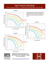
Gas Pressure Boosting Drive air pressure: 80 psig - Process gas supply pressure: 40 to 100 psig 54AAV24 240 The following graphs show the booster’s maximum discharge flowrate for a given set of operating conditions. The drive air pressure is held at 80 psi while the and the process gas supply pressure varies. Discharge pressure [psig] Square M I D W E S T 1 1-1/2"2 0 3 4 5 6 7 PRESSURE Flowrate [SCFM] SY S T E M S Flowrate [SCFM] Discharge pressure [psig] Discharge Pressure [psig] Midwest Pressure Systems, Inc. 850 Transport Drive, Valparaiso, IN 46383 Phone 219-462-0070 2" Square
Open the catalog to page 7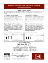
Booster Accessories: Drive air controls Drive air filter and regulator Purpose of drive air controls Drive air controls add a 5 micron filter and regulator to the air supply line. The regulator allows air supply pressure to be reduced before entering the drive section of the booster. Reducing the drive air pressure has two main benefits. 1. Decrease the discharge pressure MPS boosters are designed to deliver the maximum flow and discharge pressure for a given set of operating conditions. For most applications the maximum discharge pressure is higher than required. Reducing the drive air...
Open the catalog to page 8
Booster systems with receiver tanks Receiver Tank Benefits 1. Pulsation Dampening During operating the discharge line will experience about ± 2 psi due to the lag time between piston strokes. The pulsations may effect the consistency of sensitive equipment down stream of the booster. Adding a receiver tank will drastically reduce the pulsations down to ± 0.5 psi. Pulsations can be completely removed from the discharge line by adding a regulator after the receiver tank. 2. Extra storage A receiver tank allows for excess air/gas storage which helps manage surges or sudden flow rate demands. The...
Open the catalog to page 9


