
- Catalogs
- Microwave Product Divison
- Optimizing Test Boards for 50 GHz End Launch Connectors

Optimizing Test Boards for 50 GHz End Launch Connectors

Optimizing Test Boards for 50 GHz End Launch Connectors
This document analyzes test boards used to evaluate microwave performance, focusing on loss characteristics and bandwidth improvements. It involves different board designs, including microstrip and grounded coplanar waveguide (GCPWG) structures, tested up to 50 GHz.
An Agilent 8510D network analyzer was used for measurements, with a frequency range from DC to 50 GHz. Calibration involved a full 12-term SOLT with sliding loads, and data verification was conducted using an Anritsu 37297 network analyzer.
Southwest Microwave, Inc. aimed to optimize test boards for their end launch connectors, focusing on board layout design variables affecting microwave performance. The study expanded to include a comprehensive evaluation of GCPWG and microstrip lines.
The evaluation compared GCPWG and microstrip lines using SMI end launch connectors, including 3-D simulations based on a previous board design effective up to 45 GHz.
Microstrip lines on 30 mil Rogers 4350 boards face issues like dispersion and radiated loss above 30 GHz. GCPWG offers more stable impedance and reduced radiated loss, making it suitable for higher frequency applications.
The connectors, model 1492-02A-5, are designed for multi-layer boards with a 2.4 mm female connector and a 10 mil diameter circuit launch pin. They feature a slight interference fit for good contact without soldering.
The original GCPWG test board showed a characteristic loss glitch starting at 45 GHz. This board served as a baseline for evaluating the performance of the connectors.
The connector assemblies, model number 1492-02A-5, are designed for use on single-layer boards and multi-layer boards where the top layer is the microwave layer. They do not require soldering and are compatible with any board thickness.
The original 30 mil coplanar test board, fabricated in 2003, and its reproduction in 2007, were analyzed for performance. Both boards showed similar results, with a notable glitch in insertion loss at 45 GHz. The VSWR increased gently through 50 GHz.
Simulations using CST Microwave Studio® (CST MWS) were conducted to predict the performance of the test boards. The simulations showed good correlation with actual measured data, particularly in terms of insertion loss and VSWR characteristics.
Two taper designs were evaluated to improve the match at the launch. The first taper design worsened the match, while the optimized second taper design showed improved results, with a smoother insertion loss up to 45 GHz.
The study explored the impact of via spacing on bandwidth. Closer via spacing increased the frequency response of the board. Test boards with varying numbers of vias (3, 7, 13, and 25) were analyzed, showing improved performance with decreased via spacing.
- Board Design: The boards are designed with specific trace and ground configurations to optimize performance. Adjustments such as tapering traces and via placement are used to improve bandwidth and match.
- Testing Methodology: Measurements are conducted across a frequency range from 0.249 GHz to 50 GHz, focusing on parameters like S21 (insertion loss) and VSWR (Voltage Standing Wave Ratio).
- Improving Match: Tapering traces on Board 5d improved match, as evidenced by reduced VSWR through 50 GHz.
- Bandwidth Enhancement: Closer via placement on Board 2 increased bandwidth, confirmed by smoother insertion loss curves.
- Loss Characteristics: Different board designs exhibit distinct loss behaviors. Microstrip boards show more radiated loss at high frequencies, while GCPWG boards have higher line loss but less radiated loss.
- Microstrip Boards: Loss increases with frequency, with distinct slopes indicating board and radiated losses. For example, Board 15c shows a loss of -0.367 dB at 5 GHz and -12.634 dB at 50 GHz.
- GCPWG Boards: Exhibit a linear loss curve over frequency, with higher board loss compared to microstrip boards. Board 12b shows a loss of -0.919 dB at 5 GHz and -6.239 dB at 50 GHz.
The study concludes that the choice between microstrip and GCPWG depends on application requirements. Microstrip is preferable for longer lines where loss is a concern, while GCPWG is better for short lines requiring bandwidth and isolation. This analysis aids in understanding the trade-offs in microwave board design.
Detailed test results for various boards, including serial numbers and specific configurations, are provided to support the findings.
Catalog excerpts

The Performance Leader in Microwave Connectors Optimizing Test Boards for 50 GHz End Launch Connectors Grounded Coplanar Launches and Through Lines on 30 mil Rogers 4350 with Comparison to Microstrip Southwest Microwave, Inc. www.southwestmicrowave.com
Open the catalog to page 1
Southwest Microwave, Inc. Optimizing Test Boards for 50 GHz End Launch Connectors: Grounded Coplanar Launches and Through Lines on 30 mil Rogers 4350 with Comparison to Microstrip Bill Rosas, Product Engineering Manager, Southwest Microwave, Inc. Copyright © 2007 by Southwest Microwave, Inc. and Bill Rosas. All rights reserved. Petra Microwave®, Ltd., Rogers Corporation®, CST®-Computer Simulation Technology, and CST Microwave Studio® 2006 are all registered trademarks of their respective companies. Southwest Microwave, Inc. • Tempe, Arizona 85284 USA • 480-783-0201 • www.southwestmicrowav
Open the catalog to page 2
Table of Contents Test Equipment and Techniques . . . . . . . . . . . . . . . . . . . . . . . . . . . . . . . . . . . . . . . . 2 Analyzer Workstation (HP 8510C) . . . . . . . . . . . . . . . . . . . . . . . . . . . . . . . . . . . 2 Southwest Microwave Standard S-Parameter Plot . . . . . . . . . . . . . . . . . . . . . . . . 3 Electrical Performance . . . . . . . . . . . . . . . . . . . . . . . . . . . . . . . . . . . . . . . . 3 Purpose . . . . . . . . . . . . . . . . . . . . . . . . . . . . . . . . . . . . . . . . . . . . . . . . . . . . . . . . . . . . 4 Scope of the Evaluation . . . . ....
Open the catalog to page 3
Test Equipment and Techniques An Agilent 8510D network analyzer was used for most of the published measurements (in the loss section an Agilent PNA was used). The test port connectors used were 2.4 mm connectors and the frequency range for all measurements was DC to 50 GHz. Calibration was a full 12-term SOLT calibration with sliding loads. The TDR measurements were set up as low pass step in real units. All of the data was taken from the same calibration. Some internal verification of data was done on an Anritsu 37297 network analyzer. Analyzer Workstation (HP 8510C) ► 12-term SOLT calibration....
Open the catalog to page 4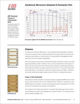
Southwest Microwave Standard S-Parameter Plot S-parameter data: The format of the data is S11 on the bottom of the graph in VSWR with scale of 0.2 per division, and S21 on the top of the graph in Log Mag with a scale of 1 dB per division. SMI Standard Format of S-Parameter Data Test data original 30 mil GCPWG test board (Serial Number Ø). Purpose For many years Southwest Microwave, Inc. has manufactured field replaceable connectors and launch accessories where connector performance was easily verified by measuring two connectors back-to-back as a two-port device. The responsibility for packaging...
Open the catalog to page 5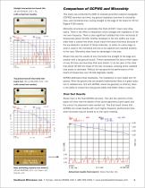
Comparison of GCPWG and Microstrip Straight microstrip test board 15c, 30 mil RO4350, S/N = 51, (with actual test results). This study was conducted by (SMI) to evaluate grounded coplanar waveguide (GCPWG) launches and lines, top ground (coplanar) launches to microstrip lines, and microstrip lines running straight to the edge of the board on 30 mil Rogers 4350 boards. Microstrip structures on substrates this thick (0.030”) have many drawbacks. There is the effect of dispersion which changes the impedance of the line over frequency. There is also significant radiated loss from microstrip at frequencies...
Open the catalog to page 6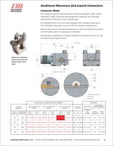
SOUTHWEST MICROWAVE Actual two connectors used for all of the test results found in this paper. Connector Model The connectors used are SMI end launch connector assemblies, model number 1492-02A-5. These connectors were designed for single-layer and multi-layer boards where the top layer is the microwave layer. The 1492-02A-5 has a 2.4 mm female connector and a transition block with a 10 mil diameter circuit launch pin and a 63.5 mil diameter coaxial ground. Because they were for multi-layer boards there is a 20 mil overhang of the ground over the board to catch the top ground of the board. No...
Open the catalog to page 7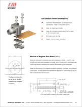
End Launch Connector Features: ► Southwest Microwave end Launch connector assemblies, model number 1492-02A-5. ► Used on single-layer boards. ► Used on multi-layer boards where the top layer is the microwave layer. ► No soldering is needed. ► Usable with any board thickness. Review of Original Test Board (2003) When the end launch connectors were first introduced in 2003, a one-inch long GCPWG test board was developed for testing. One of these original test boards was used in this study to establish the baseline performance of the connectors. Below are the results of the original end launch connector...
Open the catalog to page 8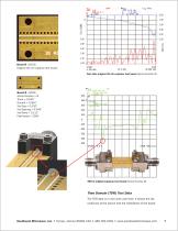
Board Ø (2003) Original 30 mil coplanar test board. Test data original 30 mil coplanar test board (Serial Number Ø). Board Ø (2003) Serial Number = Ø Trace = 0.045” Ground = 0.064” Via Size = 0.020” Via Spacing = 0.040” Via Rows = 0.112” Fabricated = 2003 TDR of original coplanar test board (Serial Number Ø). Time Domain (TDR) Test Data The TDR data is in real units over time. It shows the discontinuity at the launch and the impedance of the board. Southwest Microwave, Inc. • Tempe, Arizona 85284 USA • 480-783-0201 • www.southw
Open the catalog to page 9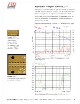
Reproduction of Original Test Board (2007) This reproduction was fabricated in the same lot in 2007 as the test boards used in the rest of this study. The purpose is to tie the results of this lot of boards to the results from the original test board fabricated in 2003. Below are the results of the reproduction of the original test board. The results are very similar to the original board including the glitch in the insertion loss at 45 GHz. The VSWR slowly rises through 45 GHz to 1.6:1 as on the original board. Board 1 (2007) Serial Number = 19 Trace = 0.045” Ground = 0.064” Via Size = 0.020”...
Open the catalog to page 10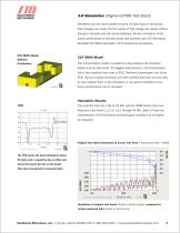
3-D Simulation (Original GCPWG Test Board) Simulation can be used to predict results of these types of structures then changes are made and the results of that change are viewed without having to fabricate and test actual hardware. Decent correlation of the known performance of this test board was achieved with CST Microwave Studio® (CST MWS) Simulation. CST provided the simulations. CST MWS Model Without Connectors CST MWS Model The 3-D simulation model is created by only looking at the transition blocks and the test board. The biggest discontinuity in the transmission line is the transition...
Open the catalog to page 11All Microwave Product Divison catalogs and technical brochures
 SSBP
SSBP24 Pages
 0.9 mm SuperMini
4 Pages


