
- Catalogs
- microsonic
- mic+ ultrasonic sensors


mic+ ultrasonic sensors

mic+ ultrasonic sensors
The mic+ ultrasonic sensors by microsonic GmbH are designed for precise distance measurement in industrial applications. They come in four variants with five sensing ranges, featuring digital displays, IO-Link interfaces, and automatic synchronization.
- Device Variants: Four variants with sensing ranges from 30 mm to 8 m.
- Resolution: 0.025 mm to 2.4 mm depending on the range.
- Outputs: Options include 1 or 2 switching outputs (pnp or npn), analogue output (4–20 mA and 0–10 V), and combinations thereof.
- Operating Voltage: 9–30 V DC with reverse polarity protection.
- Temperature Compensation: Integrated for accuracy.
- Protection Class: IP 67 for harsh environments.
- TouchControl: Digital display and buttons for easy configuration.
- Synchronization and Multiplex Operation: Supports up to ten sensors simultaneously, with options for more using SyncBox1.
- Teach-in Functionality: Simplifies setup of switching points and analogue outputs.
- LinkControl: PC configuration via LinkControl adapter and software.
- Software Filters: Ten-stage filter options for environments with wave movements or obstructions.
- Switching Hysteresis: Adjustable settings for outputs.
- LED Display: Can be dimmed or turned off.
The sensors are ideal for automation tasks, level measurements, and environments with potential interference from adjacent sensors.
- Transducer Frequency: 320 kHz or 400 kHz depending on the model.
- Blind Zone: 30 mm to 65 mm.
- Operating Range: 250 mm to 600 mm.
- Accuracy: ± 1% with internal temperature compensation.
The mic+ ultrasonic sensors provide a robust solution for industrial measurement needs, offering high precision, flexibility, and ease of use with advanced features like synchronization and multiplex operation.
Operating voltage ranges from 9 to 30 V DC with reverse polarity protection. The sensors have a low no-load current consumption and are designed to handle a switching frequency of up to 25 Hz.
The sensors are housed in materials like brass sleeve, nickel-plated, and stainless steel, with plastic parts made from PBT and TPU. The ultrasonic transducer is made from polyurethane foam and epoxy resin with glass contents, ensuring durability and protection (IP 67) against environmental factors.
The sensors operate in temperatures ranging from -25°C to +70°C and can be stored at temperatures between -40°C to +85°C. They are lightweight, with weights varying from 150 g to 270 g depending on the model.
Available accessories include KST5A-2/M12, KST5A-5/M12, BF-30, UF-90/M30, LCA-2, and SyncBox1, enhancing the functionality and installation of the sensors.
Catalog excerpts
extract from our online catalogue: mic+ ultrasonic sensors current to: 2026-10-08 microsonic GmbH / Phoenixseestraße 7 / 44263 Dortmund / Germany / T +49 231 975151-0 / F +49 231 975151-51 / E [email protected] microsonic® ist eine eingetragene Marke der microsonic GmbH. Alle Rechte vorbehalten. Änderungen vorbehalten.
Open the catalog to page 1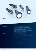
mic+mic+ sensors are available in four device variants with five different sensing ranges. Highlights > Digital display with direct measured value output in mm/cm or % > IO-Link interface > for support of the new industry standard > Numeric configuration of the sensor using digital display > permits complete advance configuration of the sensor > Automatic synchronisation and multiplex operation > for simultaneous operation of up to ten Sensors in close quarters > UL Listed to Canadian and US safety standards Basics > 1 Push-Pull switching output > pnp or npn basis > 1 or 2 switching outputs >...
Open the catalog to page 2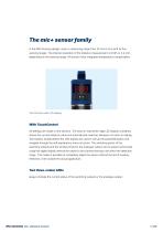
The mic+ sensor family in the M30 housing design covers a measuring range from 30 mm to 8 m with its five sensing ranges. The internal resolution of the distance measurement is 0.025 or 2.4 mm, depending on the sensing range. All sensors have integrated temperature compensation. TouchControl with LED display With TouchControl All settings are made on the sensors. The easy-to-read three-digit LED display constantly shows the current distance value and automatically switches between mm and cm display. Two buttons located below the LED display are used to call up the parameterisation and navigate...
Open the catalog to page 3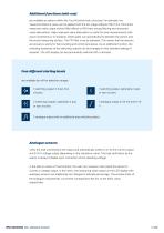
Additional functions (add-ons) are available as options within the TouchControl menu structure: For example, the measured distance value can be applied with the ten-stage software filter from F00 (direct measured value output without filter effect) to P09 (very strong filtering and measured value attenuation). High measured value attenuation is useful for level measurements with wave movements or in situations where parts can sporadically fly between the sensor and the actual measuring surface. The F01 filter is set as standard. This means that the sensors are preset ex works for fast counting...
Open the catalog to page 4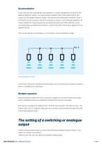
Synchronisation of up to ten sensors automatically also operates in a mixed configuration of sensors with different detection ranges. The measurement repetition rate is then determined by the sensor with the largest detection range. If the sensors are electrically connected via pin 5 of the M12 circular connector, the synchronisation is active. In synchronised operation, all sensors initiate the measuring process at exactly the same time. With relatively narrow mounting distances between the sensors, a sensor may also receive echo signals from an adjacent sensor. This can be used as an advantage,...
Open the catalog to page 5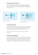
In the microsonic Teach-in process the object to be detected must be placed in the desired distance (1) to the sensor. The button assigned to the output must then be pressed until appears on the LED display. Finally, the Teach-in procedure must be confirmed by a further short keystroke. Ready. Teach-in of a switching point Teach-in of an analogue characteristic curve or a window with two switching points To set an analogue output the object to be detected must first be placed on the sensor-close window limit (1) and the key assigned to the output must be pressed until appears on the display....
Open the catalog to page 6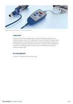
Sensor connected to the PC via LCA-2 for programming LinkControl consists of the LinkControl adapter and the LinkControl software and allows the mic+ sensors to be set up using a PC or laptop under all common Windows® operating systems. All settings from the TouchControl menu can be read out during operation, edited on the PC, temporarily stored and written back to the sensor. In particular, the two measurement recorders for visualising the distance values help in the development of solutions for complex automation tasks. IO-Link integrated in version 1.1 for sensors with switching output. mic+...
Open the catalog to page 7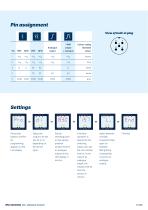
View of built-in plug Pin assignment1 PNP Colour coding Analogue output Standard Pin PNP NPN PNP NPN output + analogue colour Press both buttons until Pro for programming appears on the LED display. Select the output to be set (d1, d2 or IU, depending on the sensor type). switching point (or the sensor-proximal window limit for an analogue output) on the LED display in mm/cm. If window operation is desired for the switching output, also set the rear window limit (or, in the case of an analogue output, the window limit far from the sensor) in mm/cm. Select between Finished. miCrOSOniC mic+ ultrasonic...
Open the catalog to page 8
For numerical input, the object to be scanned does not have to be within the sensor's detection range! You have special requirements? Nothing as simple as that. With us, you can easily find an individual solution. Let us talk about your application: +49 231 97 51 51-82. mic+ ultrasonic sensors
Open the catalog to page 9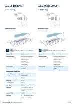
scale drawing operating mode proximity switch/reflective reflective barrier window mode analogue distance measurement operating mode proximity switch/reflective reflective barrier window mode analogue distance measurement particularities Display means of measurement echo propagation time pending on the analogue window accuracy ± 1 % (temperature drift in ternally compensated) particularities stainless steel version miCrOSOniC mic+ ultrasonic sensors 10 / 102
Open the catalog to page 10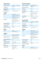
switching hysteresis switching frequency response delay delay prior to availability operating temperature storage temperature weight 5-pin M12 initiator plug analogue output current: 4-20 mA / voltage: 0-10 V (at UB > 15 V), short-circuit-proof switchable rising/falling switching output NOC/NCC adjustable, short- synchronisation input brass sleeve, nickel-plated, plastic parts, PBT, TPU polyurethane foam, epoxy resin with glass contents stainless steel cable connection (on request) means of measurement echo propagation time pending on the analogue window accuracy ± 1 % (temperature drift in ternally...
Open the catalog to page 11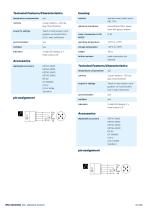
Technical Features/Characteristics play (TouchControl) scope for settings Teach-in and numeric confi guration via TouchControl LCA-2 with LinkControl Accessories housing material stainless steel, plastic parts ultrasonic transducer polyurethane foam, epoxy resin with glass contents further versions cable connection (on Technical Features/Characteristics play (TouchControl) scope for settings Teach-in and numeric confi guration via TouchControl LCA-2 with LinkControl miCfO/OniC mic+ ultrasonic sensors
Open the catalog to page 12All Microsonic catalogs and technical brochures
 LCA-2
LCA-28 Pages
 pico+ ultrasonic sensors
42 Pages
 Online Catalogue ultrasonic sensors
172 Pages
 cube ultrasonic sensors
17 Pages
 zws ultrasonic sensors
47 Pages
 wms ultrasonic distance sensors
10 Pages
 ucs ultrasonic sensors
9 Pages
 sks ultrasonic proximity switch
15 Pages
 crm+ ultrasonic level sensors
38 Pages
 pico+TF ultrasonic level sensors
42 Pages
 nero ultrasonic proximity switch
53 Pages
 bks+ ultrasonic edge sensors
8 Pages
 nano M12 ultrasonic sensor
15 Pages
 lcs+ ultrasonic sensors
15 Pages
 bks ultrasonic edge sensors
9 Pages
 mic ultrasonic sensors
27 Pages
 lpc+ ultrasonic sensors
42 Pages
 lcs ultrasonic sensors
15 Pages
 hps+ ultrasonic level sensors
20 Pages
 esp-4 label/splice sensor
13 Pages



- Microsonic proximity sensor
- Level probe
- Liquid level sensor
- Cylindrical proximity sensor
- Microsonic IP67 proximity sensor
- Analog level sensor
- Industrial detector
- DC proximity sensor
- Digital output level sensor
- Vessel level sensor
- Microsonic distance sensor
- Stainless steel level sensor
- Plastic proximity sensor
- Threaded proximity sensor
- M12 proximity sensor
- PNP proximity sensor
- Water level sensor
- Rectangular proximity sensor
- IP67 level sensor
- Analog detector