- Catalogs
- microsonic
- lcs ultrasonic sensors
- Company
- Products
- Catalogs
- News & Trends
- Exhibitions
lcs ultrasonic sensors

lcs ultrasonic sensors
- Up to 3 PNP switching outputs.
- Automatic synchronization for simultaneous operation of up to ten sensors.
- Analogue output options of 4–20 mA and 0–10 V with automatic switching.
- Three detection ranges with measurement capabilities from 30 mm to 2 m.
- Microsonic Teach-in on pin 5 for easy configuration.
- High resolution of 0.18 mm and temperature compensation.
- Operating voltage range of 9–30 V.
- LinkControl for PC-based sensor configuration.
- Design: Cuboidal with flat housing and lateral sound exit.
- Measurement Method: Echo propagation time measurement.
- Transducer Frequency: Ranges from 200 kHz to 400 kHz depending on the model.
- Operating Temperature: -25°C to +70°C, with storage temperature from -40°C to +85°C.
- Protection Class: IP 65 according to EN 60529.
- Material: PBT housing with polyurethane foam and epoxy resin transducer.
- Connection: 5-pin M12 initiator plug.
- Proximity switch/reflective mode.
- Window mode for specific detection zones.
- Teach-in capabilities for single switching points, two-way reflective barriers, and window configurations.
- Switching Outputs: PNP, adjustable NOC/NCC, short-circuit-proof.
- Analogue Outputs: 4-20 mA and 0-10 V, switchable rising/falling.
- Response Time: Varies from 32 ms to 110 ms depending on the model.
- Indicators: Two or three-color LEDs for status indication.
- LCS-25/DD/QP: 30-350 mm range, 2 PNP outputs.
- LCS-25/DDD/QP: 30-350 mm range, 3 PNP outputs.
- LCS-25/IU/QP: 30-350 mm range, analogue output.
- LCS-35/DD/QP: 65-600 mm range, 2 PNP outputs.
- LCS-35/DDD/QP: 65-600 mm range, 3 PNP outputs.
- LCS-35/IU/QP: 65-600 mm range, analogue output.
- LCS-130/DD/QP: 200-2000 mm range, 2 PNP outputs.
- Measuring Range: 200 - 2,000 mm
- Design: Cuboidal with flat housing and lateral sound exit
- Operating Modes: Proximity switch/reflective mode, analogue distance measurements
- Transducer Frequency: 200 kHz
- Blind Zone: 200 mm
- Operating Range: 1,300 mm
- Maximum Range: 2,000 mm
- Resolution: 0.18 mm to 0.57 mm, depending on the model
- Reproducibility: ± 0.15%
- Accuracy: ± 1% with internal temperature compensation
- Operating Voltage: 9 - 30 V DC with reverse polarity protection
- Connection Type: 5-pin M12 initiator plug
- Protection Class: IP 65 according to EN 60529
- Operating Temperature: -25°C to +70°C
- Storage Temperature: -40°C to +85°C
- Weight: 200 g
- Switching Outputs: 3 x PNP, 200 mA, NOC/NCC adjustable, short-circuit-proof
- Analogue Output: Current: 4-20 mA / Voltage: 0-10 V, short-circuit-proof
- Switching Frequency: 6 Hz
- Response Time: 110 ms
- Delay Prior to Availability: < 300 ms
- Indicators: Three-colour LEDs
- Material: PBT housing, polyurethane foam, epoxy resin with glass contents for the transducer
- Temperature Compensation: Yes
- Teach-in Functionality: Available via com input on pin 5
- Synchronisation: Available on certain models
- Multiplex: Not available
Catalog excerpts

Extract from our online catalogue: lcs ultrasonic sensors Current to: 2025-01-27 microsonic GmbH / Phoenixseestraße 7 / 44263 Dortmund / Germany / T +49 231 975151-0 / F +49 231 975151-51 / E [email protected] microsonic® is a registered trademark of microsonic GmbH. All rights reserved.
Open the catalog to page 1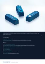
Ultrasonic sensors in the Ics series in cuboidal housing with lateral sound exit are available in three device variants with three different detection ranges. HIGHLIGHTS > Up to 3 pnp switching outputs > Automatic synchronisation > for simultaneous operation of up to ten sensors in close quarters > 2 or 3 switching outputs in pnp variant > Analogue output 4-20 mA and 0-10 V > with automatic switching between current and voltage outputs > 3 detection ranges with a measurement range of 30 mm to 2 m > LinkControl > for configuration of sensors from a PC micro/onic lcs ultrasonic sensors
Open the catalog to page 2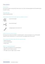
have a block-like plastic housing with four fixation bores, two of which are already equipped with M4 threaded bushings for eased mounting. indicate all operating statuses. (Com input), the Ics sensors are set (Teach-in): Switched output D1 is set by connecting pin 5 to +UB, while switched output D2 is set by connecting pin 5 to -UB. Also the sensors with analogue output are set via pin 5. > Single switching point > Two-way reflective barrier > Place object to be detected (1) at the desired distance > Apply +UB to pin 5 for about 3 seconds > Then apply +UB to pin 5 again for about 1 seconds micro/onic...
Open the catalog to page 3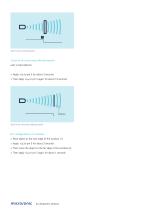
Teach-in of a switching point Teach-in of a two-way reflective barrier with a fixed reflector Apply +UB to pin 5 for about 3 seconds Then apply +UB to pin 5 again for about 10 seconds Teach-in of a two-way reflective barrier Place object at the near edge of the window (1) Apply +UB to pin 5 for about 3 seconds Then move the object to the far edge of the window (2) Then apply +UB to pin 5 again for about 1 seconds
Open the catalog to page 4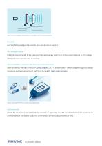
Teach-in of an analogue characteristic or a window with two switching points NCC/NOC and rising/falling analogue characteristic curve can also be set via pin 5. The analogue sensor checks the load connected to the output and then automatically switch to 4–20 mA current output or 0–10 V voltage output to ensure maximum ease of handling. The Ics-25/DDD is equipped with three pnp switched outputs which are set with the help of the Link-Control adapter LCA-2. In addition to this “offline” programming, all Ics sensors can also be parameterised on the PC with the LCA-2 and the Link-Control software ....
Open the catalog to page 5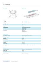
measuring range design operating mode ultrasonic-specific means of measurement transducer frequency blind zone operating range maximum range resolution reproducibility accuracy proximity switch/reflective mode reflective barrier window mode flat housing lateral sound exit echo propagation time measurement ± 1 % (temperature drift internally compensated) operating voltage UB 9 - 30 V d.c., reverse polarity protection type of connection 5-pin M12 initiator plug
Open the catalog to page 7
output 1 switching output NOC/NCC adjustable, short-circuit-proof output 2 switching output NOC/NCC adjustable, short-circuit-proof delay prior to availability teach-in input ultrasonic transducer operating temperature storage temperature polyurethane foam, epoxy resin with glass contents IP 65 technical features/characteristics temperature compensation controls com input control input Teach-in via com input on pin 5 LCA-2 with LinkControl flat housing lateral sound exit micro/onic lcs ultrasonic sensors
Open the catalog to page 8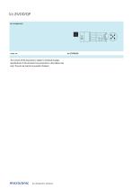
The content of this document is subject to technical changes. Specifications in this document are presented in a descriptive way only. They do not warrant any product features.
Open the catalog to page 9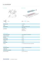
measuring range design operating mode particularities ultrasonic-specific means of measurement transducer frequency blind zone operating range maximum range resolution reproducibility accuracy proximity switch/reflective mode window mode 3 switched outputs flat housing lateral sound exit echo propagation time measurement ± 1 % (temperature drift internally compensated) operating voltage UB 9 - 30 V d.c., reverse polarity protection type of connection 5-pin M12 initiator plug
Open the catalog to page 10
output 1 switching output NOC/NCC adjustable, short-circuit-proof output 2 switching output NOC/NCC adjustable, short-circuit-proof output 3 switching output NOC/NCC adjustable, short-circuit-proof delay prior to availability < 300 ms inputs ultrasonic transducer operating temperature storage temperature polyurethane foam, epoxy resin with glass contents IP 65 3 switched outputs flat housing lateral sound exit technical features/characteristics temperature compensation controls
Open the catalog to page 11
The content of this document is subject to technical changes. Specifications in this document are presented in a descriptive way only. They do not warrant any product features.
Open the catalog to page 12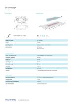
measuring range design operating mode particularities ultrasonic-specific means of measurement transducer frequency blind zone operating range maximum range resolution reproducibility accuracy analogue distance measurements flat housing lateral sound exit echo propagation time measurement ± 1 % (temperature drift internally compensated) operating voltage UB 9 - 30 V d.c., reverse polarity protection type of connection 5-pin M12 initiator plug
Open the catalog to page 13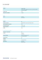
output 1 analogue output current: 4-20 mA / voltage: 0-10 V (at UB > 15 V), short-circuit-proof switchable rising/falling delay prior to availability < 300 ms inputs teach-in input ultrasonic transducer operating temperature storage temperature polyurethane foam, epoxy resin with glass contents IP 65 technical features/characteristics temperature compensation controls com input control input Teach-in via com input on pin 5 LCA-2 with LinkControl flat housing lateral sound exit micro/onic lcs ultrasonic sensors
Open the catalog to page 14
The content of this document is subject to technical changes. Specifications in this document are presented in a descriptive way only. They do not warrant any product features.
Open the catalog to page 15All Microsonic catalogs and technical brochures
 pico+ ultrasonic sensors
78 Pages
 Online Catalogue ultrasonic sensors
172 Pages
 cube ultrasonic sensors
33 Pages
 zws ultrasonic sensors
81 Pages
 wms ultrasonic distance sensors
20 Pages
 ucs ultrasonic sensors
13 Pages
 sks ultrasonic proximity switch
21 Pages
 crm+ ultrasonic level sensors
75 Pages
 pico+TF ultrasonic level sensors
41 Pages
 nero ultrasonic proximity switch
100 Pages
 bks+ ultrasonic edge sensors
10 Pages
 nano M12 ultrasonic sensor
19 Pages
 lcs+ ultrasonic sensors
24 Pages
 bks ultrasonic edge sensors
13 Pages
 mic ultrasonic sensors
46 Pages
 lpc+ ultrasonic sensors
77 Pages
 LCA-2
LCA-211 Pages
 hps+ ultrasonic level sensors
44 Pages
 esp-4 label/splice sensor
23 Pages
 hps+25/DIU/TC/E/G1
44 Pages
 crm+25/D/TC/E
75 Pages
 mic+ ultrasonic sensors
191 Pages


- Microsonic proximity sensor
- Level probe
- Liquid level sensor
- Cylindrical proximity sensor
- Analog level sensor
- Microsonic IP67 proximity sensor
- Industrial detector
- Digital output level sensor
- Vessel level sensor
- DC proximity sensor
- Microsonic distance sensor
- Stainless steel level sensor
- Plastic proximity sensor
- Threaded proximity sensor
- IP67 level sensor
- Water level sensor
- Rectangular proximity sensor
- PNP proximity sensor
- Solid level sensor
- M12 proximity sensor