
- Catalogs
- microsonic
- lcs+ ultrasonic sensors


lcs+ ultrasonic sensors
lcs+ ultrasonic sensors
- Dimensions: 62 mm x 62 mm x 37.2 mm
- Detection Range: Up to 8 meters
- Outputs: 1 Push-Pull switching output or 2 pnp switching outputs; Analogue output 4–20 mA and 0–10 V
- Operating Voltage: 9–30 V DC
- Temperature Range: Operating -25°C to +70°C, Storage -40°C to +85°C
- Protection Class: IP67
- IO-Link Interface: Supports the latest industry standards for enhanced device communication.
- Smart Sensor Profiles: Provides transparency between IO-Link devices.
- Teach-in Functionality: Easy setup using buttons T1 and T2 for configuring switching points and analogue characteristics.
- Synchronization and Multiplex Mode: Allows simultaneous operation of up to ten sensors.
- Temperature Compensation: Ensures accuracy across varying temperatures.
- Single Switching Point
- Two-way Reflective Barrier
- Window Mode
- Resolution: 0.18 mm to 2.4 mm depending on the model
- Reproducibility: ±0.15%
- Accuracy: ±1% with internal temperature compensation
Catalog excerpts
extract from our online catalogue: lcs+ ultrasonic sensors current to: 2026-10-09 microsonic GmbH / Phoenixseestraße 7 / 44263 Dortmund / Germany / T +49 231 975151-0 / F +49 231 975151-51 / E [email protected] microsonic® ist eine eingetragene Marke der microsonic GmbH. Alle Rechte vorbehalten. Änderungen vorbehalten.
Open the catalog to page 1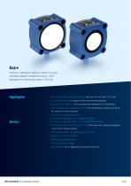
lcs+The lcs+ ultrasonic sensors come in a very compact square-shaped housing - with analogue or switching output + IO-Link. Highlights > Very compact housing dimensions > only 62 mm x 62 mm x 37.2 mm > IO-Link interface > for support of the new industry standard > Smart Sensor Profiles > more transparency between IO-Link Devices > Synchronisation and multiplex mode > for simultaneous operation of up to ten sensors in close quarters > 8 m maximum detection range > UL Listed to Canadian and US safety standards Basics > 1 Push-Pull switching output, or 2 pnp switching outputs > Analogue output 4-20...
Open the catalog to page 2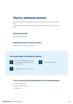
The lcs+ ultrasonic sensors have a block-like plastic housing with a base area of only 62 x 62 mm and four fastening bores. The sensors are Listed to applicable UL Standards and requirements by UL for Canada and the US. Two dual colour LEDs show all operating statuses. Using the two Teach-in buttons T1 and T2 the lcs+ sensors can be easily set (Teach-in). Three output stages are available for selection: 1 Push-Pull switching output with pnp or npn switching technology with IO- Link interface The Ics+ sensors with switching output have three operating modes: Single switching point Two-way reflective...
Open the catalog to page 3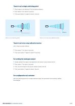
> Place object to be detected (1) at the desired distance > Push button T2 for about 3 seconds > Then push button T2 again for about 1 second Teach-in of a switching point Teach-in of a two-way reflective barrier with a fixed mounted reflector > Push button T1 for about 3 seconds > Then push button T1 again for about 10 seconds > Initially position the object to be detected to the sensor-close window limit (1) > Push button T1 for about 3 seconds > Then move the object to the sensor-distant window limit (2) > Then push button T1 again for about 1 second with two switching points on a single switched...
Open the catalog to page 4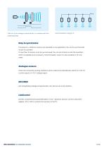
Teach-in of an analogue characteristic or a window with two switching points Easy to synchronise If several lcs+ ultrasonic sensors are operated in one application, the can be synchronised via pin 5 to prevent. If more than 10 sensors must be synchronised, this can be carried out with the SyncBox1 , which is available as an accessory. Synchronisation via pin 5 is also possible in IO-Link mode. Analogue sensors check the connected working resistance at the output and automatically switch to 4–20 mA current output or 0–10 V voltage output. NCC/NOC and rising/falling analogue characteristics can...
Open the catalog to page 5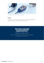
Sensor connected to the PC via LCA-2 for programming IO-Link Ultrasonic sensors lcs+340/F/A and lcs+600/F/A have a Push-Pull switching output and support IO-Link in version 1.1 as well as the Smart Sensor profile. You have special requirements? Nothing as simple as that. With us, you can easily find an individual solution. Let us talk about your application: +49 231 97 51 51-82. lcs+ ultrasonic sensors
Open the catalog to page 6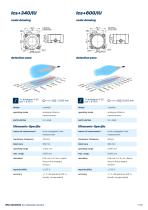
scale drawing scale drawing 1 x analogue 4-20 mA + 0-10 V 1 x analogue 4-20 mA + 0-10 V design operating mode analogue distance operating mode analogue distance means of measurement echo propagation time ding on the analogue window accuracy ± 1 % (temperature drift in ternally compensated) means of measurement echo propagation time ding on the analogue window accuracy ± 1 % (temperature drift in ternally compensated) miCrOSOniC lcs+ ultrasonic sensors
Open the catalog to page 7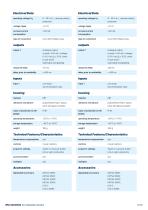
Electrical Data operating voltage UB 9 - 30 V d.c., reverse polarity type of connection 5-pin M12 initiator plug output 1 analogue output current: 4-20 mA / voltage: 0-10 V (at UB > 15 V), short-circuit-proof switchable rising/falling delay prior to availability < 450 ms synchronisation input ultrasonic transducer polyurethane foam, epoxy resin with glass contents Technical Features/Characteristics scope for settings Teach-in via push-button Electrical Data operating voltage UB 9 - 30 V d.c., reverse polarity type of connection 5-pin M12 initiator plug output 1 analogue output current: 4-20 mA...
Open the catalog to page 8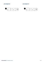
lcs+ ultrasonic sensors
Open the catalog to page 9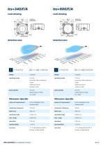
scale drawing scale drawing detection zone detection zone operating mode operating mode proximity switch/reflective proximity switch/reflective reflective barrier reflective barrier window mode window mode IO-Link Smart Sensor Profile Ultrasonic-Specific means of measurement Smart Sensor Profile Ultrasonic-Specific echo propagation time echo propagation time measurement transducer frequency transducer frequency blind zone blind zone operating range operating range ternally compensated) lcs+ ultrasonic sensors ternally compensated)
Open the catalog to page 10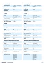
Electrical Data operating voltage UB 9 - 30 V d.c., reverse polarity type of connection 5-pin M12 initiator plug output 1 switching output delay prior to availability < 380 ms synchronisation input ultrasonic transducer polyurethane foam, epoxy resin with glass contents Technical Features/Characteristics scope for settings Teach-in via push-button LCA-2 with LinkControl IO-Link Electrical Data operating voltage UB 9 - 30 V d.c., reverse polarity type of connection 5-pin M12 initiator plug output 1 switching output delay prior to availability < 450 ms synchronisation input ultrasonic transducer...
Open the catalog to page 11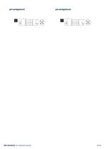
lcs+ ultrasonic sensors
Open the catalog to page 12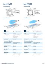
designoperating modeparticularitiesUltrasonic-Specificmeans of measurement transducer frequency blind zone operating range max. range resolution reproducibility accuracy proximity switch/reflective mode reflective barrier window mode UL Listed echo propagation time measurement ± 1 % (temperature drift internally compensated) transducer frequency blind zone operating range max. range resolution reproducibility accuracy proximity switch/reflective mode reflective barrier window mode UL Listed echo propagation time measurement ± 1 % (temperature drift internally compensated)
Open the catalog to page 13All Microsonic catalogs and technical brochures
 LCA-2
8 Pages
 pico+ ultrasonic sensors
42 Pages
 Online Catalogue ultrasonic sensors
172 Pages
 cube ultrasonic sensors
17 Pages
 zws ultrasonic sensors
47 Pages
 wms ultrasonic distance sensors
10 Pages
 ucs ultrasonic sensors
9 Pages
 sks ultrasonic proximity switch
15 Pages
 crm+ ultrasonic level sensors
38 Pages
 pico+TF ultrasonic level sensors
42 Pages
 nero ultrasonic proximity switch
53 Pages
 bks+ ultrasonic edge sensors
8 Pages
 nano M12 ultrasonic sensor
15 Pages
 bks ultrasonic edge sensors
9 Pages
 mic ultrasonic sensors
27 Pages
 lpc+ ultrasonic sensors
42 Pages
 lcs ultrasonic sensors
15 Pages
 hps+ ultrasonic level sensors
20 Pages
 esp-4 label/splice sensor
13 Pages
 mic+ ultrasonic sensors
102 Pages
- Microsonic proximity sensor
- Level probe
- Liquid level sensor
- Cylindrical proximity sensor
- Microsonic IP67 proximity sensor
- Analog level sensor
- Industrial detector
- DC proximity sensor
- Digital output level sensor
- Vessel level sensor
- Microsonic distance sensor
- Stainless steel level sensor
- Plastic proximity sensor
- Threaded proximity sensor
- M12 proximity sensor
- PNP proximity sensor
- Water level sensor
- Rectangular proximity sensor
- IP67 level sensor
- Analog detector