
Catalog excerpts
Digital Potentiometers Design Guide Supporting digital potentiometer applications, including: mechanical potentiometer replacement, amplifiers with offset and trimming, band pass filtering with offset and gain trimming, programmable filter, Wheatstone bridge trimming and general embedded system design techniques. Design ideas in this guide use the following devices. A complete device list and corresponding data sheets for these products can be found at www.microchip.com. www.microchip.com/analog Analog and Interface Product Solutions 6-bit 7-bit 8-bit Single Single Dual Quad Single Dual Quad MCP401X MCP402X MCP401X MCP40D1X MCP413X MCP414X MCP453X MCP423X MCP424X MCP463X MCP464X MCP433X MCP434X MCP443X MCP444X MCP415X MCP416X MCP455X MCP456X MCP425X MCP426X MCP465X MCP466X MCP435X MCP436X MCP445X MCP446X
Open the catalog to page 1
2 Digital Potentiometer Design Guide Microchip’s Family of Digital Potentiometers Microchip offers a range of devices that allow the customer to select a device that is a best fit for their application. Some of the selection options include: ¡ A wide range of resistor values – RAB resistance (typical) from 2.1 kÙ to 100 kÙ ¡ Step resolution – 6-bit – 7-bit – 8-bit ¡ Serial interfaces – Up/Down – SPI – I2C™ ¡ Memory types – Volatile – Non-volatile ¡ Resistor network configurations – Potentiometer (resistor divider) – Rheostat (variable resistor) ¡ Single, dual and quad potentiometer options...
Open the catalog to page 2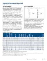
Digital Potentiometer Design Guide 3 Low Power Applications Many applications are power sensitive. This is because they are battery powered or design goals on the power supply. Microchip Technology’s digital potentiometer families are low power, with the maximum IDD as low as 1 ìA in some devices. This current is when the serial interface is inactive and a non-volatile memory write cycle is not active. This current does not include any current through the resistor network (the A, B and W pins). The 1 uA max IDD devices include the MCP4011, MCP4012, MCP4013, MCP4014, MCP4021, MCP4022,...
Open the catalog to page 3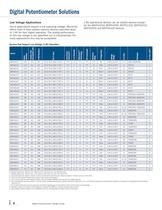
4 Digital Potentiometer Design Guide Low Voltage Applications Some applications require a low operating voltage. Microchip offers most of their volatile memory devices specified down to 1.8V for their digital operation. The analog performance at this low voltage is not specified, but is characterized. For many applications this may be acceptable. Digital Potentiometer Solutions Devices that Support Low Voltage (1.8V) Operation Device Serial Interface Volatile (Vol) Non-Volatile (NV) # RS Resistors Rs Ù (typ.) Zero-Scale/ Full-Scale(3) # of Channels WiperLock™ Technology HV Commands Shutdown...
Open the catalog to page 4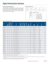
Digital Potentiometer Design Guide 5 Digital Potentiometer Solutions Package Area (mm2) Comment MSOP ~14.7 DFN (3x3) ~9 39% Smaller than MSOP SOT-23 ~8.3 44% Smaller than MSOP DFN (2x3) ~6 59% Smaller than MSOP 33% Smaller than DFN 3x3 SC70 ~4.2 71% Smaller than MSOP 55% Smaller than DFN 3x3 30% Smaller than DFN 2x3 SOT-23 3 mm 2.95 mm DFN 3 mm 3 mm DFN 3 mm 2 mm SC70 2.1 mm 2 mm MSOP 4.9 mm 3 mm Small Footprint Applications Some applications have package size limitations and require devices with the smallest footprint possible. Microchip offers several devices in small footprint packages....
Open the catalog to page 5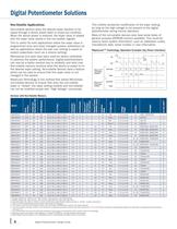
6 Digital Potentiometer Design Guide This inhibits accidental modification of the wiper setting, as long as the high voltage is not present to the digital potentiometer during normal operation. Many of the non-volatile devices also have some bytes of general purpose EEPROM memory available. This could be used to store system information, such as calibration codes, manufacture date, serial number or user information. Non-Volatile Applications Non-volatile devices allow the desired wiper position to be saved through a device power down or brown-out condition. When the device power is...
Open the catalog to page 6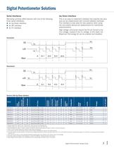
Digital Potentiometer Design Guide 7 Digital Potentiometer Solutions Serial Interfaces Microchip currently offers devices with one of the following three serial interfaces: ¡ An Up/Down interface ¡ An SPI interface ¡ An I2C interface Increment Decrement Up/Down Interface This is an easy to implement interface that requires two pins and can be implemented with minimal software overhead. This interface is also easy for test systems when using the non-volatile devices as replacements for mechanical potentiometers. High voltage commands require the CS pin forced to the VIHH voltage, instead of...
Open the catalog to page 7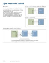
8 Digital Potentiometer Design Guide SPI Interface This is also an easy to implement interface, that requires three or four I/O pins. The additional pins allow data to be read back from the device or to allow device daisy chaining. Daisy chaining allows the SPI interface to update all devices in that chain at the same time. Many microcontrollers offer this interface as a hardware module, further simplifying the code development. High voltage commands require the CS pin forced to the VIHH voltage, instead of the VIL voltage. In this state, the WiperLock Technology bit can be enabled and...
Open the catalog to page 8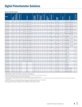
Digital Potentiometer Design Guide 9 Digital Potentiometer Solutions Devices with SPI Interface Device Serial Interface Volatile (Vol) Non-Volatile (NV) # RS Resistors Rs Ù (typ.) Zero-Scale/ Full-Scale(3) # of Channels WiperLock™ Technology HV Commands Shutdown Mode Configuration Voltage Range # of Pins Packages IDD max (ìA)(5) MCP4131(2) SPI Vol 128 39.1/78.1/390.6/781.3 Y/Y 1 N Y(9) Y(8) Pot 1.8V to 5.5V(6) 8 PDIP, SOIC, MSOP, DFN 5 MCP4132(2) SPI Vol 128 39.1/78.1/390.6/781.3 Y/Y 1 N Y(9) Y(8) Rheo 1.8V to 5.5V(6) 8 PDIP, SOIC, MSOP, DFN 5 MCP4141(2) SPI NV 128 39.1/78.1/390.6/781.3 Y/Y...
Open the catalog to page 9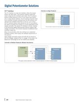
10 Digital Potentiometer Design Guide Digital Potentiometer Solutions I2C™ Interface The I2C interface is a two wire interface, where the output drivers are open drain. This protocol supports reads and writes using only the interface’s two wires. The I2C protocol allows multiple devices on the I2C bus, where each device has a unique device address. The I2C protocol requires more host controller firmware overhead than the SPI protocol, but requires less hardware resources (2 pins vs. 3 or 4 pins). The I2C protocol allows many devices on the I2C bus without the need to increase the number of...
Open the catalog to page 10All Microchip Technology Inc. catalogs and technical brochures
-
 MicroSolutions
8 Pages
-
 DSA1001/3/4
22 Pages
-
 Embedded Computing Solutions
4 Pages
-
 ATmegaET128
469 Pages
-
 RE46C140
13 Pages
-
 ATmega4809
74 Pages
-
 16-bit MCUs and DSCs
20 Pages
-
 MPLAB® Harmony
12 Pages
-
 32-bit Microcontroller Family
20 Pages
-
 32-bit MPU
8 Pages
-
 UCS100X Family Sell Sheet
2 Pages
-
 PIC32 Graphics Sell Sheet
2 Pages
-
 PIC32 Audio Sell Sheet
2 Pages
-
 PIC1XF150X/155X Sell Sheet
2 Pages
-
 MRF24WG0MA/MB Sell Sheet
2 Pages
-
 MCP19111 Sell Sheet
2 Pages
-
 LAN9730(i) Sell Sheet
2 Pages
-
 Connectivity Brochure
16 Pages
-
 bit Embedded Control Solutions
20 Pages


Archived catalogs
-
 Serial Memory Products
16 Pages
-
 LIN J2602 Transceiver
32 Pages
-
 Infrared Encoder/Decoder
36 Pages
-
 MCP794XX I2C™ RTCC Brochure
2 Pages
-
 MCP1640/B/C/D
32 Pages
-
 Motor Control Solutions Brochure
12 Pages
-
 Power Management MCP1525/41
20 Pages
-
 PIC32 Overview Brochure
6 Pages
-
 8-bit PIC® Microcontrollers
16 Pages


