RE46C140
1 /13Pages

RE46C140
1 /13Pages
Catalog excerpts

R&E International A Subsidiary of Microchip Technology Inc. RE46C140 CMOS Photoelectric Smoke Detector ASIC with Interconnect and Timer Mode Product Specification General Description The RE46C140 is low power CMOS photoelectric type smoke detector IC. With minimal external components this circuit will provide all the required features for a photoelectric type smoke detector. The design incorporates a gain selectable photo amplifier for use with an infrared emitter/detector pair. An internal oscillator strobes power to the smoke detection circuitry for 100us every 10 seconds to keep standby current to a minimum. If smoke is sensed the detection rate is increased to verify an alarm condition. A high gain mode is available for push button chamber testing. Internal Power On Reset Low Quiescent Current Consumption Available in 16L PDIP, 16L N SOIC or 16L W SOIC ESD Protection on all Pins Interconnect up to 40 Detectors 10 Minute Timer for Sensitivity Control Temporal Horn Pattern Internal Low Battery and Chamber Test Compatible with Allegro A5366 UL Recognized per File S24036 Available in Standard Packaging or RoHS Compliant Pb Free Packaging. A check for a low battery condition and chamber integrity is performed every 43 seconds when in standby. The temporal horn pattern supports the NFPA 72 emergency evacuation signal. An interconnect pin allows multiple detectors to be connected such that when one units alarms, all units will sound. An internal 10 minute timer can be used for a reduced sensitivity mode. The RE46C140 is recognized by Underwriters Laboratories for use in smoke detectors that comply with specification UL217 and UL268. ABSOLUTE MAXIMUM RATINGS PARAMETER Supply Voltage Input Voltage Range Except FEED, IO FEED Input Voltage Range IO Input Voltage Range Input Current except FEED Operating Temperature Storage Temperature Maximum Junction Temperature Stresses beyond those listed under Absolute Maximum Ratings may cause permanent damage to the device. These are stress ratings only and operation at these conditions for extended periods may affect device reliability. This product utilizes CMOS technology with static protection; however proper ESD prevention procedures should be used when handling this product. Damage can occur when exposed to extremely high static electrical charge.
Open the catalog to page 1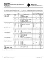
RE46C140 CMOS Photoelectric Smoke Detector ASIC with Interconnect and Timer Mode Product Specification Note 1: Does not include Q3 emitter current.
Open the catalog to page 2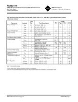
RE46C140 CMOS Photoelectric Smoke Detector ASIC with Interconnect and Timer Mode Product Specification Note 1: Not production tested Typical values are for design information and are not guaranteed. Limits over the specified temperature range are not production tested and are based on characterization data.
Open the catalog to page 3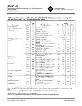
RE46C140 CMOS Photoelectric Smoke Detector ASIC with Interconnect and Timer Mode Product Specification Note 1 - See timing diagram for Horn Temporal Pattern Note 2 - During the timer mode the LED Period is 10.5 seconds. The LED period will return to a 43 seconds at the conclusion of the timer mode. Note 3 - TPOSC and TON2 are 100% production tested. All other timing is guaranteed by functional testing. Typical values are for design information and are not guaranteed. Limits over the specified temperature range are not production tested and are based on characterization data.
Open the catalog to page 4
RE46C140 CMOS Photoelectric Smoke Detector ASIC with Interconnect and Timer Mode Product Specification R&E International A Subsidiary of Microchip Technology Inc.
Open the catalog to page 5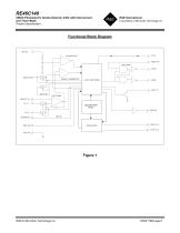
RE46C140 CMOS Photoelectric Smoke Detector ASIC with Interconnect and Timer Mode Product Specification horn_d river SMOKE COMPARATOR BIAS AND POWER RESET Figure 1 2009 © Microchip Technology Inc. DS22179B-page6
Open the catalog to page 6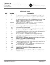
RE46C140 CMOS Photoelectric Smoke Detector ASIC with Interconnect and Timer Mode Product Specification C2 DETECT STROBE VDD IRED IO HB HS FEED LED COSC ROSC VSS The capacitor connected to this pin sets the photo amplifier gain (high) for the push-to-test and chamber sensitivity test. The size of this capacitor will depend on the chamber background reflections. A=1+(C1/10) where C1 is in pF. The gain should be <10000. The capacitor connected to this pin sets the photo amplifier gain (normal) during standby. The value of this capacitor will depend on the smoke sensitivity required. A=1+(C2/10)...
Open the catalog to page 7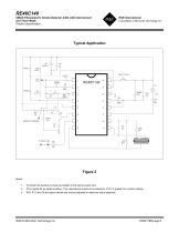
RE46C140 CMOS Photoelectric Smoke Detector ASIC with Interconnect and Timer Mode Product Specification R&E International A Subsidiary of Microchip Technology Inc. Typical Application C3 should be located as close as possible to the device power pins. C3 is typical for an alkaline battery. This capacitance should be increased to 4.7uF or greater for a carbon battery. R10, R11 and C6 are typical values and may be adjusted to maximize sound pressure.
Open the catalog to page 8
RE46C140 CMOS Photoelectric Smoke Detector ASIC with Interconnect and Timer Mode Product Specification R&E International A Subsidiary of Microchip Technology Inc. CIRCUIT DESCRIPTION AND APPLICATION NOTES Note: All timing references are nominal. See electrical characteristics for limits. Standby Internal Timing – With the external components specified in the typical application figure for ROSC and COSC the internal oscillator has a nominal period of 10mS. Normally the analog circuitry is powered down to minimize standby current (typically 4uA at 9V). Once every 10 seconds the detection circuitry...
Open the catalog to page 9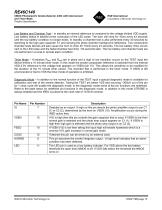
RE46C140 CMOS Photoelectric Smoke Detector ASIC with Interconnect and Timer Mode Product Specification Low Battery and Chamber Test - In standby an internal reference is compared to the voltage divided VDD supply. Low battery status is latched at the conclusion of the LED pulse. The horn will chirp for 10ms every 43 seconds until the low battery condition no longer exists. In standby a chamber test is also performed every 40 seconds by switching to the high gain capacitor C1 and sensing the photo chamber background reflections. Two consecutive chamber tests failures will also cause the horn to...
Open the catalog to page 10All Microchip Technology Inc. catalogs and technical brochures
 MicroSolutions
8 Pages
 DSA1001/3/4
22 Pages
 Embedded Computing Solutions
4 Pages
 ATmegaET128
469 Pages
 ATmega4809
74 Pages
 16-bit MCUs and DSCs
20 Pages
 MPLAB® Harmony
12 Pages
 32-bit Microcontroller Family
20 Pages
 32-bit MPU
8 Pages
 UCS100X Family Sell Sheet
2 Pages
 PIC32 Graphics Sell Sheet
2 Pages
 PIC32 Audio Sell Sheet
2 Pages
 PIC1XF150X/155X Sell Sheet
2 Pages
 MRF24WG0MA/MB Sell Sheet
2 Pages
 MCP19111 Sell Sheet
2 Pages
 LAN9730(i) Sell Sheet
2 Pages
 Connectivity Brochure
16 Pages
 bit Embedded Control Solutions
20 Pages


Archived catalogs
 Serial Memory Products
16 Pages
 LIN J2602 Transceiver
32 Pages
 Infrared Encoder/Decoder
36 Pages
 MCP794XX I2C™ RTCC Brochure
2 Pages
 MCP1640/B/C/D
32 Pages
 Motor Control Solutions Brochure
12 Pages
 Power Management MCP1525/41
20 Pages
 PIC32 Overview Brochure
6 Pages
 8-bit PIC® Microcontrollers
16 Pages


- Liebherr signal amplifier
- Liebherr power amplifier
- Wireless module
- Potentiometer
- Liebherr compact converter
- Liebherr serial converter
- Industrial converter
- Manual potentiometer
- Crystal oscillator
- Measuring amplifier
- Liebherr voltage amplifier
- DC amplifier
- Low-noise amplifier
- Power converter
- Precision potentiometer
- Liebherr microcontroller
- Analog amplifier
- Liebherr current amplifier
- Digital converter
- Fast converter