- Catalogs
- Microchip Technology Inc.
- Infrared Encoder/Decoder
Infrared Encoder/Decoder
1 /36Pages

Infrared Encoder/Decoder
1 /36Pages
Catalog excerpts
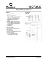
© 2007 Microchip Technology Inc. DS21618B-page 1 MCP2120 Features • Supports with IrDA® Physical Layer Specification (version 1.3) • UART to IR Encoder/Decoder - Interfaces with IrDA Compliant Transceivers - Used with any UART, including standard 16550 UART and microcontroller UART • Transmit/Receive formats supported: - 1.63ìs • Hardware or Software Baud rate selection - Up to IrDA standard 115.2 kbaud operation - Up to 312.5 kbaud operation (at 20 MHz) - Low power mode • Pb-free packaging CMOS Technology • Low-power, high-speed CMOS technology • Fully static design • Low voltage operation • Commercial and Industrial temperature ranges • Low power consumption - < 1 mA @ 3.3V, 8 MHz (typical) - 3 mA typical @ 5.0V when disabled Pin Diagrams Block Diagram PDIP, SOIC MCP2120 VDD OSC1/CLKIN OSC2 RESET RXIR TXIR MODE VSS EN TX RX BAUD0 BAUD1 BAUD2 1234567 14 13 12 11 10 98 Decode TX TXIR RX RXIR EN MCP2120 Logic Baud Rate BAUD2 Generator BAUD1 BAUD0 MODE Encode Infrared Encoder/Decoder
Open the catalog to page 1
MCP2120 DS21618B-page 2 © 2007 Microchip Technology Inc. NOTES:
Open the catalog to page 2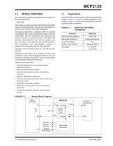
© 2007 Microchip Technology Inc. DS21618B-page 3 MCP2120 1.0 DEVICE OVERVIEW This document contains device specific information for the following device: • MCP2120 This device is a low-cost, high-performance, fully-static infrared encoder/decoder. This device sits between a UART and an infrared (IR) optical transceiver. The data received from a standard UART is encoded (modulated), and output as electrical pulses to the IR Transceiver. The IR Transceiver also receives data which it outputs as electrical pulses. The MCP2120 decodes (demodulates) these electrical pulses and then the data is transmitted...
Open the catalog to page 3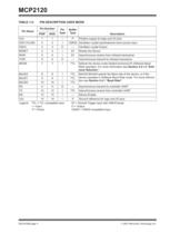
MCP2120 DS21618B-page 4 © 2007 Microchip Technology Inc. TABLE 1-2: PIN DESCRIPTION USER MODE Pin Name Pin Number Pin Type Buffer PDIP SOIC Type Description VDD 1 1 — P Positive supply for logic and I/O pins OSC1/CLKIN 2 2 I CMOS Oscillator crystal input/external clock source input OSC2 3 3 O — Oscillator crystal Output RESET 4 4 I ST Resets the Device RXIR 5 5 I ST Asynchronous receive from infrared transceiver TXIR 6 6 O — Asynchronous transmit to infrared transceiver MODE 7 7 I TTL Selects the device mode (Data/Command) for Software Baud Rate operation. For more information see Section 2.4.1.2...
Open the catalog to page 4
© 2007 Microchip Technology Inc. DS21618B-page 5 MCP2120 2.0 DEVICE OPERATION The MCP2120 is a low cost infrared Encoder/Decoder. The baud rate is user selectable to standard IrDA baud rates between 9600 baud to 115.2 kbaud. The maximum baud rate is 312.5 kbaud. 2.1 Power-up Any time that the device is powered up, the Device Reset Timer delay (parameter 32) must occur before any communication with the device is initiated. This is from both the infrared transceiver side as well as the controller UART interface. 2.2 Device Reset The MCP2120 is forced into the reset state when the RESET pin is in...
Open the catalog to page 5
MCP2120 DS21618B-page 6 © 2007 Microchip Technology Inc. 2.4.1.2 Software Selection When the BAUD2:BAUD0 pins are configured as ’111’ the MCP2120 defaults to a baud rate of FOSC / 768. To place the MCP2120 into Command Mode, the MODE pin must be at a low level. When in this mode, any data that is received by the MCP2120’s UART is "echoed" back to the controller and no encoding/ decoding occurs. The echoed data will be skewed less than 1 bit time (see parameter IR141). When the MODE pin goes high, the device is returned to Data Mode where the encoder/decoder is in operation. Table 2-2 shows the...
Open the catalog to page 6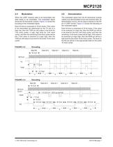
© 2007 Microchip Technology Inc. DS21618B-page 7 MCP2120 2.5 Modulation When the UART receives data to be transmitted, the data needs to be modulated. This modulated signal drives the IR transceiver module. Figure 2-2 shows the encoding of the modulated signal. Each bit time is comprised of 16-bit clocks. If the value to be transmitted (as determined by the TX pin) is a logic low, then the TXIR pin will output a low level for 7-bit clock cycles, a logic high level for 3-bit clock cycles, and then the remaining 6-bit clock cycles will be low. If the value to transmit is a logic high, then the...
Open the catalog to page 7
MCP2120 DS21618B-page 8 © 2007 Microchip Technology Inc. 2.7 Encoding/Decoding Jitter and Offset Figure 2-4 shows the jitter and offset that is possible on the RX pin and the TXIR pin. Jitter is the possible variation of the desired edge. Offset is the propagation delay of the input signal (RXIR or TX) to the output signal (RX or TXIR). The first bit on the output pin (on RX or TXIR) will show jitter compared to the input pin (RXIR or TX), but all remaining bits will be a constant distance. 2.8 Minimizing Power The device can be placed in a low power mode by disabling the device (holding the...
Open the catalog to page 8
© 2007 Microchip Technology Inc. DS21618B-page 9 MCP2120 3.0 DEVELOPMENT TOOLS The MCP212X Developer’s Daughter Board is used to evaluate and demonstrate the MCP2122 or the MCP2120 IrDA® Standard Encoder/Decoder devices. A header allows the MCP212X Developer’s Daughter Board to be jumpered easily into systems for development purposes. The MCP212X Developer’s Daughter Board is designed to interface to several of the “new” low cost PIC® Demo Boards. These include the PICDEM HPC Explorer Demo board, the PICDEM FS USB Demo board, and the PICDEM LCD Demo board. When the MCP212X Developer’s Daughter...
Open the catalog to page 9
MCP2120 DS21618B-page 10 © 2007 Microchip Technology Inc. NOTES:
Open the catalog to page 10
MCP2120 DS21618B-page 12 © 2007 Microchip Technology Inc. FIGURE 4-1: Voltage-Frequency Graph, -40°C TA +85°C 6.0 2.5 4.0 3.0 0 3.5 4.5 5.0 5.5 4 10 Frequency (MHz) VDD 20 (Volts) 2.0 8 12 16 FMAX = (8.0 MHz/V) (VDDAPPMIN -2.5V) + 4 MHz Note: VDDAPPMIN is the minimum voltage of the MCP2120 in the application.
Open the catalog to page 12
© 2007 Microchip Technology Inc. DS21618B-page 13 MCP2120 4.1 DC Characteristics DC Characteristics Standard Operating Conditions (unless otherwise specified) Operating Temperature –40°C TA +85°C (industrial) Param. No. Sym Characteristic Min Typ(1) Max Units Conditions D001 VDD Supply Voltage 2.5 — 5.5 V See Figure 4-1 D002 VDR RAM Data Retention Voltage (2) 2.5 — — V Device Oscillator/Clock stopped D003 VPOR VDD Start Voltage to ensure Power-on Reset — VSS — V D004 SVDD VDD Rise Rate to ensure Power-on Reset 0.05 — — V/ms D010 IDD Supply Current (3) —————— 0.8 0.6 0.4 34 4.5 1.4 1.0 0.8 7 12...
Open the catalog to page 13All Microchip Technology Inc. catalogs and technical brochures
 MicroSolutions
8 Pages
 DSA1001/3/4
22 Pages
 Embedded Computing Solutions
4 Pages
 ATmegaET128
469 Pages
 RE46C140
13 Pages
 ATmega4809
74 Pages
 16-bit MCUs and DSCs
20 Pages
 MPLAB® Harmony
12 Pages
 32-bit Microcontroller Family
20 Pages
 32-bit MPU
8 Pages
 UCS100X Family Sell Sheet
2 Pages
 PIC32 Graphics Sell Sheet
2 Pages
 PIC32 Audio Sell Sheet
2 Pages
 PIC1XF150X/155X Sell Sheet
2 Pages
 MRF24WG0MA/MB Sell Sheet
2 Pages
 MCP19111 Sell Sheet
2 Pages
 LAN9730(i) Sell Sheet
2 Pages
 Connectivity Brochure
16 Pages
 bit Embedded Control Solutions
20 Pages


Archived catalogs
 Serial Memory Products
16 Pages
 LIN J2602 Transceiver
32 Pages
 MCP794XX I2C™ RTCC Brochure
2 Pages
 MCP1640/B/C/D
32 Pages
 Motor Control Solutions Brochure
12 Pages
 Power Management MCP1525/41
20 Pages
 PIC32 Overview Brochure
6 Pages
 8-bit PIC® Microcontrollers
16 Pages


- Liebherr signal amplifier
- Liebherr power amplifier
- Wireless module
- Potentiometer
- Liebherr compact converter
- Liebherr serial converter
- Industrial converter
- Manual potentiometer
- Crystal oscillator
- Measuring amplifier
- Liebherr voltage amplifier
- DC amplifier
- Low-noise amplifier
- Power converter
- Precision potentiometer
- Analog amplifier
- Liebherr current amplifier
- Digital converter
- Fast converter