- Catalogs
- Microchip Technology Inc.
- ATmegaET128
ATmegaET128
1 /469Pages

ATmegaET128
1 /469Pages
Catalog excerpts

Extended Temperature 8-bit AVR Microcontroller, 3.3V, 8 MHz with 128 KB Flash, 4 KB EEPROM, 4 KB SRAM, 10-bit ADC, TWI, RTC, 16-bit PWM, USART, SPI and 16-bit Timer/Counter The ATmegaET128 is a low-power CMOS 8-bit microcontroller based on the AVR enhanced RISC architecture. By executing powerful instructions in a single clock cycle, the ATmegaET128 achieves throughputs close to 1 MIPS per MHz. This empowers system designers to optimize the device for power consumption versus processing speed. Features • High-Performance, Low-Power AVR 8-bit Microcontroller • Advanced RISC Architecture - 133 powerful instructions - most single-clock cycle execution - 32 x 8 general-purpose working registers and peripheral control registers - Fully static operation - Up to 8 MIPS throughput at 8 MHz - On-chip 2-cycle multiplier • High Endurance Non-Volatile Memory Segments - 128 Kbytes of in-system self-programmable Flash program memory - 4 Kbytes internal SRAM - Write/Erase cycles: 10K Flash/20K EEPROM - Data retention: 10 years @ 125°C - Optional boot code section with independent lock bits • In-system programming by on-chip boot program • True Read-While-Write operation - Up to 64 Kbytes optional external memory space - Programming lock for software security - SPI interface for in-system programming • JTAG (IEEE std. 1149.1 Compliant) Interface - Boundary-scan capabilities according to the JTAG standard - Extensive on-chip debug support - Programming of Flash, EEPROM, fuses and lock bits through the JTAG interface • Peripheral Features © 2018 Microchip Technology Inc. Datasheet DS60001547A-page 1
Open the catalog to page 1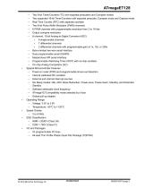
- Two 8-bit Timer/Counters (TC) with separate prescalers and Compare modes - Two expanded 16-bit Timer/Counters with separate prescaler, Compare mode and Capture mode - Real Time Counter (RTC) with separate oscillator - Two 8-bit Pulse Width Modulator (PWM) channels - 6 PWM channels with programmable resolution from 2 to 16 bits - Output compare modulator - 8-channel, 10-bit Analog-to-Digital Converter (ADC) • 8 single-ended channels • 2 differential channels with programmable gain at 1x, 10x, or 200x - Byte-oriented two-wire serial interface - Dual programmable serial USARTs - Master/slave SPI...
Open the catalog to page 2
© 2018 Microchip Technology Inc. Datasheet DS60001547A-page 3
Open the catalog to page 3
© 2018 Microchip Technology Inc. Datasheet DS60001547A-page 4
Open the catalog to page 4
© 2018 Microchip Technology Inc. Datasheet DS60001547A-page 5
Open the catalog to page 5
© 2018 Microchip Technology Inc. Datasheet DS60001547A-page 7
Open the catalog to page 7
Description The AVR core combines a rich instruction set with 32 general-purpose working registers. All 32 registers are directly connected to the Arithmetic Logic Unit (ALU), allowing two independent registers to be accessed in one single instruction executed in one clock cycle. The resulting architecture is more code efficient while achieving throughputs up to ten times faster than conventional CISC microcontrollers. The ATmegaET128 provides the following features: 128 Kbytes of In-System Programmable Flash with Read-While-Write capabilities, 4 Kbytes EEPROM, 4 Kbytes SRAM, 53 general-purpose...
Open the catalog to page 9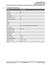
Configuration Summary © 2018 Microchip Technology Inc. Datasheet DS60001547A-page 10
Open the catalog to page 10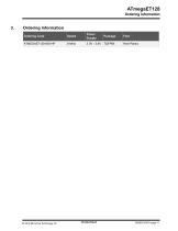
Ordering Information © 2018 Microchip Technology Inc. Datasheet DS60001547A-page 11
Open the catalog to page 11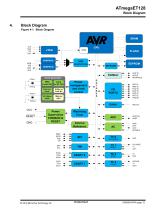
Block Diagram Figure 4-1. Block Diagram Clock generation 8MHz 8 MHz Crystal OSC Ext RC OSC Power management and clock control Power Supervision POR/BOD & RESET Watchdog Timer Internal Reference
Open the catalog to page 12
5. ATmega103 and ATmegaET128 Compatibility The ATmegaET128 device features an ATmega103 compatibility mode. As this mode requires a hardware configuration with significant differences compared to the ATmegaET128 native mode and with regard to the mapping of the RAM, I/O pins and interrupt vectors, it is not possible to have both modes available at the same time. Thus the ATmega103 compatibility mode must be selected by programming the fuse M103C. 5.1 ATmega103 Compatibility Mode (External Data Memory Mode) When the ATmega103 compatibility mode is activated, some new features in ATmegaET128 are...
Open the catalog to page 13
Pin Descriptions VCC Digital supply voltage. © 2018 Microchip Technology Inc. Datasheet DS6
Open the catalog to page 14
Port A (PA7:PA0) Port A is an 8-bit bidirectional I/O port with internal pull-up resistors (selected for each bit). The Port A output buffers have symmetrical drive characteristics with both high sink and source capability. As inputs, Port A pins that are externally pulled low will source current if the pull-up resistors are activated. The Port A pins are tristated when a reset condition becomes active, even if the clock is not running. Port A also serves the functions of various special features of the ATmegaET128 as listed in Alternate Functions of Port A. Related Links 15.3.1 Alternate Functions...
Open the catalog to page 15
Port E (PE7:PE0) Port E is an 8-bit bi-directional I/O port with internal pull-up resistors (selected for each bit). The Port E output buffers have symmetrical drive characteristics with both high sink and source capability. As inputs, Port E pins that are externally pulled low will source current if the pull-up resistors are activated. The Port E pins are tristated when a reset condition becomes active, even if the clock is not running. Port E also serves the functions of various special features of the ATmegaET128 as listed in Alternate Functions of Port E. Related Links 15.3.5 Alternate Functions...
Open the catalog to page 16
AVCC AVCC is the supply voltage pin for Port F and the A/D Converter. It should be externally connected to VCC, even if the ADC is not used. If the ADC is used, it should be connected to VCC through a low-pass filter. AREF AREF is the analog reference pin for the A/D Converter. PEN PEN is a programming enable pin for the SPI Serial Programming mode, and is internally pulled high. By holding this pin low during a Power-on Reset, the device will enter the SPI Serial Programming mode. PEN has no function during normal operation.
Open the catalog to page 17
ATmegaET128 About Code Examples About Code Examples This data sheet contains simple code examples that briefly show how to use various parts of the device. These code examples assume that the part-specific header file is included before compilation. Be aware that not all C compiler vendors include bit definitions in the header files and interrupt handling in C is compiler-dependent. Please confirm with the C compiler documentation for more details. For I/O registers located in extended I/O map, “IN”, “OUT”, “SBIS”, “SBIC”, “CBI”, and “SBI” instructions must be replaced with instructions that...
Open the catalog to page 18All Microchip Technology Inc. catalogs and technical brochures
 MicroSolutions
8 Pages
 DSA1001/3/4
22 Pages
 Embedded Computing Solutions
4 Pages
 RE46C140
13 Pages
 ATmega4809
74 Pages
 16-bit MCUs and DSCs
20 Pages
 MPLAB® Harmony
12 Pages
 32-bit Microcontroller Family
20 Pages
 32-bit MPU
8 Pages
 UCS100X Family Sell Sheet
2 Pages
 PIC32 Graphics Sell Sheet
2 Pages
 PIC32 Audio Sell Sheet
2 Pages
 PIC1XF150X/155X Sell Sheet
2 Pages
 MRF24WG0MA/MB Sell Sheet
2 Pages
 MCP19111 Sell Sheet
2 Pages
 LAN9730(i) Sell Sheet
2 Pages
 Connectivity Brochure
16 Pages
 bit Embedded Control Solutions
20 Pages


Archived catalogs
 Serial Memory Products
16 Pages
 LIN J2602 Transceiver
32 Pages
 Infrared Encoder/Decoder
36 Pages
 MCP794XX I2C™ RTCC Brochure
2 Pages
 MCP1640/B/C/D
32 Pages
 Motor Control Solutions Brochure
12 Pages
 Power Management MCP1525/41
20 Pages
 PIC32 Overview Brochure
6 Pages
 8-bit PIC® Microcontrollers
16 Pages


- Liebherr signal amplifier
- Liebherr power amplifier
- Wireless module
- Potentiometer
- Liebherr compact converter
- Liebherr serial converter
- Industrial converter
- Manual potentiometer
- Crystal oscillator
- Measuring amplifier
- Liebherr voltage amplifier
- DC amplifier
- Low-noise amplifier
- Power converter
- Precision potentiometer
- Analog amplifier
- Liebherr current amplifier
- Fast converter