- Catalogs
- Microcentric
- CB-ND & CB-NS Collet Chuck Manual
CB-ND & CB-NS Collet Chuck Manual
1 /24Pages

CB-ND & CB-NS Collet Chuck Manual
1 /24Pages
Catalog excerpts

Technical Documentation for CB-ND & CB-NS Collet Chucks
Open the catalog to page 1
Contact & Service Information . . . . . . . . . . . . . . . . . . . . . . . . . . . . . . . . . . . . . . . . . . . . . . . . . . . . . . . . 1 Introduction . . . . . . . . . . . . . . . . . . . . . . . . . . . . . . . . . . . . . . . . . . . . . . . . . . . . . . . . . . . . . . . . . . . . . . 2 Precautions for Safe Operation . . . . . . . . . . . . . . . . . . . . . . . . . . . . . . . . . . . . . . . . . . . . . . . . . . . . . . . 3 Recommended Tightening Torque for Mounting Screws . . . . . . . . . . . . . . . . . . . . . . . . . . . . . . . . . . . . 7 Chucking Guidelines 5.1 Accuracy...
Open the catalog to page 2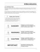
MicroCentric 2.0 INTRODUCTION MicroCentric Collet Chucks offer unmatched accuracy and long term performance. The information contained in this manual, if properly followed, will enable you to take full advantage of your chuck's capabilities. We recommend you read through this entire manual to familiarize yourself with the installation and operation of MicroCentric collet chucks before installing and using your chuck. We also suggest you keep this manual at hand for future reference. Safety Alert Symbol This is the industry "Safety Alert Symbol". This symbol is used to call your attention to items...
Open the catalog to page 3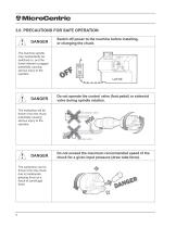
Switch off power to the machine before installing, or changing the chuck. The machine spindle may inadvertantly be switched on, and the turret indexed or jogged potentially causing serious injury to the operator. Do not operate the control valve (foot pedal) or solenoid valve during spindle rotation. The workpiece will be thrown from the chuck potentially causing serious injury to the operator.
Open the catalog to page 4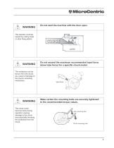
Do not start the machine with the door open. The operator could be injured by cutting chips or other flying debris.
Open the catalog to page 5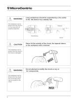
Long workpieces should be supported by a live center in the tail stock or by a steady rest. The workpiece can be thrown from the chuck if it is too long and not properly supported. t\ CAUTION Never hit the outside of the chuck, the tapered sleeve, or the workpiece with a hammer The workpiece can be thrown from the chuck if the chuck is damaged. WARNING Do not attempt to modify the chuck or any or its' components. The workpiece can be thrown from the chuck due to damage which may be caused to the chuck.
Open the catalog to page 6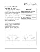
MicroCentric 5.0 CHUCKING GUIDELINES 5.1 ACCURACY AND RUNOUT To obtain high accuracy workholding it is important to correctly match the collet diameter to the workpiece diameter being clamped. Each workpiece has a dimensional tolerance, and to achieve best chucking accuracy the collet should be sized to correspond to the largest diameter of the workpiece’s range. Figure 5.1 illustrates the principle of single line contact by each collet segment. This condition will enable you to obtain minimum workpiece runout. When a workpiece is clamped by a collet that has a diameter that is smaller than the...
Open the catalog to page 9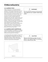
5.2 CLAMPING FORCE Higher clamping force is generally required for roughing applications as compared to finishing operations. The clamping characteristics of a collet are enhanced by serrations, which will permitted higher rates of metal removal at the same draw tube force as compared to a smooth bore collet. The frictional force between the collet and workpiece or bar stock can also be increased by applying a carbide grit or diamond particle plating to the clamping surface of the collet. Sharp serrations that penetrate the surface of the workpiece provide the greatest clamping force to prevent...
Open the catalog to page 10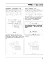
MicroCentric 5.4 END STOPPING A WORKPIECE Part stops can be mounted inside CB-ND, CB-NS, and CB-K series collet chucks to provide end location of the workpiece. Figure 5.3 illustrates a typical part stop configuration using a stop plate mounted inside the collet chuck body. Part stops, locators, and ejectors are available for specific workpiece applications. Contact MicroCentric’s technical sales staff for information. The clamping force of a collet is affected by centrifugal force as spindle speed increases. Never exceed the maximum spindle speed recommended for a specific collet chuck model....
Open the catalog to page 11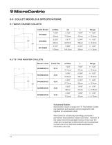
6.2 "S" PAD MASTER COLLETS Master Collet Vulcanized Rubber MicroCentric Quick Change and "S" Pad Master Collets are hardened and precision ground segments held together by vulcanized rubber. MicroCentric's vulcanizing technology produces a permanent bond between rubber and metal. However, if the rubber becomes damaged during normal use, the collet can be returned to MicroCentric and revulcanized. Contact one of our technical sales associates for information and cost.
Open the catalog to page 12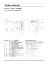
Collet Chuck Body Assembly To replace a collet chuck with a worn tapered collet sleeve, a collet chuck body assembly is available. A chuck body assembly consists of the following: Item 4 - Chuck Body Item 5 - Tapered Collet Sleeve Item 2 - Collet Sleeve Mounting Screws Item 10 - Radial Adjusting Screws Item 11 - Tapered Set Screw Item 12 - Face Seal Item 13- Collet Sleeve Bushing Item 14 - O-Ring Item 15 - Lock Screw Item 16- Locating Key Worn tapered collet seats can also be reground. Contact one of MicroCentric's technical sales associates for information.
Open the catalog to page 14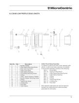
Collet Chuck Body Assembly To replace a collet chuck with a worn tapered collet sleeve, a collet chuck body assembly is available. A chuck body assembly consists of the following: Item 4 - Chuck Body Item 14 - Tapered Collet Sleeve Item 2 - Collet Sleeve Mounting Screws Item 5 - Collet Sleeve Bushing Item 7 - O-Ring Item 10- O-Ring Item 11 - Tapered Set Screw Item 12 - Locating Key Item 13- Face Seal Worn tapered collet seats can also be reground. Contact one of MicroCentric's technical sales associates for information.
Open the catalog to page 15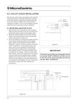
MicroCentric 9.0 COLLET CHUCK INSTALLATION MicroCentric collet chucks are supplied with a spindle mounting plate and a threaded draw tube connector to suit the machine configuration specified when the chuck was ordered. Refer to the chuck assembly drawings (on pages 13 and 14) to familiarize yourself with the chuck's components before installation. Face Runout Radial Runout 9.1 MOUNTING ADAPTER PLATE 1. Make certain that the spindle and the mounting plate are clean and free of nick or burrs that could prevent the proper seating of the adapter plate. 2. Mount the adapter plate to the machine spindle....
Open the catalog to page 16All Microcentric catalogs and technical brochures
 Precision chucks for improved
11 Pages
 5C-16C Collet Chuck
8 Pages
 LDZ Air Cylinder Catalog
12 Pages
 MBS Diaphragm Chuck Catalog
15 Pages
 S Pad Collet Chuck Catalog
15 Pages
 PPC Catalog
16 Pages
 Air Chuck Catalog
24 Pages
 General Catalog
12 Pages


Archived catalogs
 Multi Spindle Catalog
20 Pages
 General Catalog
12 Pages
 Collet Chuck Brochure
4 Pages


- Lumibird control valve
- Ball valve
- Cylinder
- Lumibird pneumatic valve
- Double-acting cylinder
- Hydraulic cylinder
- Rotary joint
- Pneumatic cylinder
- Multi-port rotary union
- Filtration unit
- Milling chuck
- Air rotary distributor
- VOC-free liquid filtration unit
- High-precision chuck
- Workpiece clamping chuck
- Steel cylinder
- Precision cylinder