- Catalogs
- MICRO-CONTROLE / Spectra-Physics
- Tunable Bandpass Fiber Optic Filter
Tunable Bandpass Fiber Optic Filter

Tunable Bandpass Fiber Optic Filter
- Specifications: The filter has a narrow bandwidth of 0.8 nm, a high tuning resolution of 0.05 nm, and a broad tuning range from 1535 to 1565 nm. It features low insertion loss (1.5 dB typical), low back-reflection (-50 dB max), and low polarization sensitivity.
- Applications: It is used for sideband noise suppression in erbium-doped fiber amplifiers (EDFA), tunable laser transmission systems, and wavelength selection for test and measurement applications.
- Design: The filter uses a thin film coating interference filter between two angled fiber optic collimators, adjustable via a high-precision micrometer.
- Ordering Information: The model TBF-1550-1.0 is available with various fiber optic connector options, including FC/SPC and FC/APC.
- Models: Three models are available: ISC, ISS, and ISU, each offering different levels of isolation and polarization mode dispersion.
- Specifications: The ISC model provides peak isolation of >40 dB, the ISS model >50 dB, and the ISU model >60 dB. All models have very low insertion loss and polarization mode dispersion.
- Design: These isolators feature an epoxy-free optical path for increased performance and reliability, and are compact for easy integration.
Catalog excerpts

P h o t o n i c s a n d I n s t r u m e n t a t i o n 365 Email: [email protected] • Web: newport.com POLARIZATION MEASUREMENT AND CONTROL LASER DIODE CONTROL LASER DIODE MOUNTS FIBER OPTIC COMPONENTS OPTICAL FIBERS AND ACCESSORIES EDUCATIONAL KITS Tunable Bandpass Fiber Optic Filter Newport’s Tunable Bandpass Fiber Optic Filter is used to adjust the center wavelength of a narrow passband within a 30 nm range around 1550 nm. A 0.8 nm tunable filter model is offered, having a 1535–1565 nm tuning range. The filter features high isolation, low insertion loss, low back-reflection and low polarization sensitivity. A thin film coating interference filter, located between two angled fiber optic collimators, is used to select the wavelength of interest, by adjusting the tilt angle of the filter with a high-precision micrometer having 0.05 nm resolution. Applications for Newport’s Tunable Bandpass Filter include: sideband noise suppression in erbium-doped fiber amplifiers (EDFA) and in tunable laser transmission systems; as well as wavelength selection for test and measurement applications. 1535 1545 1550 1555 1560 WAVELENGTH (nm) 1540 1565 LOSS (dB) 5.0 4.0 3.0 2.0 1.0 0 Maximum Typical 1535 1545 1550 1555 1560 WAVELENGTH (nm) 1540 1565 0.6 0.5 0.4 0.3 0.2 0.1 0 POLARIZATION DEPENDENT LOSS (dB) Maximum Typical • Narrow bandwidth (0.8 nm) • High tuning resolution (0.05 nm) • Broad tuning range (1535–1565 nm) • Low insertion loss (1.5 dB typical) • Low back-reflection (-50 dB max) 1.5 dB 80 70 60 50 40 30 20 10 0 TRANSMISSION (%) 1530 1540 1550 1560 1570 WAVELENGTH (nm) Specifications Model TBF-1550-1.0 Wavelength Tuning Range (nm) 1535 to 1565 Tuning Resolution, Typical (nm) 0.05 0.5 dB Bandwidth, Typical (nm) 0.8 0.5 dB Bandwidth, Maximum (nm) 3.5 20 dB Bandwidth, Maximum (nm) 3.0 Insertion Loss, Typical (dB)(1) 1.5(3) Insertion Loss, Maximum (dB)(1) 3.0(3) Back-Reflection, Maximum (dB) -50 Polarization Dependent Loss, Typical 0.05 dB, typical @ 1565 nm; 0.3 dB @ 1535 nm Center ë Stability (nm/°C) 0.005 Thermal Limit (dB/°C) 0.005 Fiber(2) 9/125 Singlemode Operating Temperature (°C) +15 to +65 Storage Temperature Range (°C) -40 to +70 1) Without fiber optic connectors 2) Filters come with standard 1 m, 3 mm loose tube jacketed fiber pigtails 3) Measured at 1565 nm [dB] Dimensions 2.72 (69.0) MAX 2.24 (57.0) 2.80 (71.0) 2.17 (55.0) 2.56 (65.0) CLR (4) TUNABLE BANDPASS FILTER [in. (mm)] Please call Newport’s Application Sales Engineers to help you determine what optical fibers or fiber optic components best meet your needs.
Open the catalog to page 1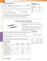
Example: FLTR-OPT-50-15-55 TBF-1550-1.0 filter with FC/SPC connector on input and FC/APC connector on output. If only a single connector is required, use the NN in the connector field designating the unterminated end (i.e. FLTR-OPT-50-15-NN). Please see the Tutorial (see page 409) for more information on fiber optic connectors available through Newport . 366 Phone: 1-800-222-6440 • Fax: 1-949-253-1680 P h o t o n i c s a n d I n s t r u m e n t a t i o n POLARIZATION MEASUREMENT AND CONTROL OPTICAL FIBERS FIBER OPTIC COMPONENTS LASER DIODE MOUNTS LASER DIODE CONTROL AND ACCESSORIES EDUCATIONAL...
Open the catalog to page 2All MICRO-CONTROLE / Spectra-Physics catalogs and technical brochures
 Precision Motion Control
27 Pages
 OPTICAL FIBER ALIGNMENT
6 Pages
 SA2_90028936F
1 Page
 10BPF10-370_ROHS
1 Page
 10BPF10-320_ROHS
1 Page
 10BPF10-310
1 Page
 M-401
M-4011 Page
 Tunable Diode Lasers
16 Pages
 Custom Component Solutions
6 Pages
 Vision IsoStation Brochure
5 Pages
 Nanopositioning Solutions
55 Pages
 newport ressource
1640 Pages
 Motion PL30
24 Pages
 CONEX-AG-LS25-27P
2 Pages
 Nanopositioners
40 Pages
 Prisms and retroreflectors
9 Pages
 Beamsplitters
34 Pages
 Spherical and aspherical lenses
35 Pages
 Optrical mirror
33 Pages
 Ultra-Low Loss SuperMirrors™
2 Pages
 Precision Right-Angle Prisms
1 Page
 Parallel Windows
1 Page
 Sapphire Windows
1 Page
 Compensated Attenuators
1 Page
 High-Energy Laser Beam Expanders
2 Pages
 High-Energy Variable Attenuators
3 Pages
 Laser Collimator
1 Page
 Gradient Index Micro Lenses
2 Pages
 Aspheric Condenser Lenses
1 Page
 Molded Glass Aspheric Lenses
3 Pages
 BK 7 Precision Bi-Convex Lenses
2 Pages
 Polarcor™ Linear Polarizers
1 Page
 Precision Linear Polarizers
1 Page
 Broadband Beam Samplers
1 Page
 Pellicle Beamsplitters
1 Page
 Plane Ruled Reflection Gratings
2 Pages
 Volume Bragg Gratings™
1 Page
 Ultrafast Laser Beam Sampler
1 Page
 Ultrafast Laser Chirped Mirrors
2 Pages
 Laser Diode Objective Lenses
1 Page
 Precision Objective Lenses
1 Page
 Reflective Microscope Objectives
2 Pages
 Systems Solutions brochure
6 Pages
 Polarization Controller, Manual
2 Pages
 Fiber Optic Depolarizers
1 Page
 Mode Scrambler
1 Page
 Index-Matching Fluid
1 Page
 Variable Ratio Couplers
2 Pages
 Fixed Fiber Optic Attenuator
1 Page
 Fiber Optic Switches
2 Pages
 Single Branch Fiber Bundles
1 Page
 Fiber Optic Isolator
2 Pages
 Photonic Crystal Fibers
4 Pages
 Oriel Multi-track Fiber Bundles
2 Pages
 Power Delivery Fibers
1 Page
 Liquid Light Guides
2 Pages
 Infrared Fibers
1 Page
 Fast Steering Mirrors
4 Pages
 Optical Delay Line Kit
1 Page
 Long Scan Autocorrelator
1 Page
 I-V Test Station
2 Pages
 Projects in Optics
2 Pages
 Projects in Interferometry
2 Pages
 Azimuth / Elevation Gimbals
2 Pages
 Air-Bearing System
2 Pages
 X-Ray Diffractometer
2 Pages
 Motion System
2 Pages
 LabLegs™ Upgrade Kits
1 Page
 UCS Series Cleanroom Tables
1 Page
 TE Series Table Enclosures
1 Page
 Oriel Integrating Spheres
5 Pages
 Oriel Inspection Probes
1 Page
 Oriel Focusing Lens Assembly
2 Pages
 Xenon Flashlamps
2 Pages
 Oriel InstaSpec X CCD
3 Pages
 Oriel Mini Monochromator
3 Pages
 Oriel 77200 1/4 m Monochromator
3 Pages
 OSM2 Series Spectrometers
2 Pages
 Oriel Optical Choppers
2 Pages
 Electronic Safety Shutters
1 Page
 Oriel Optical Shutter
1 Page
 Iris Diaphragms
1 Page
 X26 Series Mirror Mount
1 Page
 Mini Optical Rails and Carriers
2 Pages
 Slotted Bases
2 Pages
 SDS Series Angle Brackets
1 Page
 Rotation Adaptor
1 Page
 PBN Series Base Plates
1 Page
 Modular Riser Plates
1 Page
 Magnetic Bases
2 Pages
 Kinematic Stops and Nudgers
1 Page
 Kinematic Bases
2 Pages
 Fixed Height Platforms
1 Page
 EQ Series Angle Brackets
2 Pages
 Base Clamps
1 Page
 360 Series Angle Brackets
1 Page
 Rod Platforms
1 Page
 Rod Clamps
1 Page
 Posts and Post Holders
3 Pages
 Post Clamps and Accessories
1 Page
 Pedestal-Base Post Holders
2 Pages
 Modular Construction System
1 Page
 Holders for Pedestal Posts
1 Page
 Heavy Duty Rod Systems
2 Pages
 Dual Rod Systems
1 Page
 Breadboard Support Posts
1 Page
 Pedestal Post System
2 Pages
 Motorized Filter Wheels
1 Page
 Manual Filter Wheels
1 Page
 Indexed Filter Wheel Mounts
1 Page
 Filter Holders
1 Page
 Filter and Optic Holders
1 Page
 V-Blocks
1 Page
 Precision Beam Steerers
1 Page
 Polarizer Rotation Mounts
1 Page
 Pockels Cell Positioner
1 Page
 Kin-a-Flip Mount
1 Page
 Diffraction Grating Mount
2 Pages
 Cube Beamsplitter Holders
1 Page
 Beam Steerers
1 Page
 Aegis Qube™ Beam Routing System
5 Pages
 Variable Lens Holder
1 Page
 Self-Centering Lens Mounts
1 Page
 Multi-Axis Lens Positioners
4 Pages
 Lens Focusing Mount
1 Page
 Fixed Lens Mounts
1 Page
 Cylindrical Lens Holders
1 Page
 Compact Lens Positioners
1 Page
 Adjustable Lens Mounts
1 Page
 UV Objective Lenses
1 Page
 Objective Lenses
1 Page
 Infrared Lenses
1 Page
 Spherical Ball Micro Lenses
1 Page
 Three-Axis Spatial Filters
2 Pages
 Precision Singlet Lens Sets
3 Pages
 OptiSet™ Optics Sets
2 Pages
 Laser Beam Expanders
2 Pages
 Electronic Shutter System
1 Page
 UV Beam Viewer
1 Page
 Interferometer Flats
1 Page
 Light Pipe Homogenizer
1 Page
 VALUMAX® Right-Angle Prisms
1 Page
 VALUMAX® Broadband Mirrors
2 Pages
 Laser Line Dielectric Mirrors
2 Pages
 High-Energy Nd:YAG Laser Mirrors
2 Pages
 Broadband SuperMirrors™
1 Page
 Broadband Metallic Mirrors
2 Pages
 Broadband Dielectric Mirrors
2 Pages
 Oriel TE Cooler Controller
1 Page
 Oriel Current Preamplifier
1 Page
 Micro-Beam Profiler
1 Page
 Laser Beam Profiler
2 Pages
 High-Speed Photodetectors, GHz
7 Pages
 Oriel Silicon Detectors
2 Pages
 Oriel Pb and PbSe Detectors
2 Pages
 Oriel InGaAs and Ge Detectors
2 Pages
 Oriel Photomultiplier Tubes
2 Pages
 Fiber Optic Detectors
2 Pages
 PulseScout Autocorrelator
2 Pages
 Heat Control Filters
1 Page
 Colored Glass Filters
3 Pages
 Bandpass Filters
4 Pages
 Laser Line Filters
2 Pages
 Short and Long-Wave Pass Filters
2 Pages
 Oriel Order Sorting Filters
1 Page
 UZ Series Vertical Linear Stages
2 Pages
 HXP100 Hexapod
2 Pages
 BG Series Goniometric Cradles
4 Pages
 EL/EN Series Lab Jacks
1 Page
 ECN/ECR Series Lab Jacks
2 Pages
 Single-Mode Fiber Couplers
1 Page
 Multimode Fiber Couplers
2 Pages
 GRIN Lens Fiber Couplers
1 Page
 Fiber Optic Positioners
3 Pages
 BM Series Micrometers
2 Pages
 Apex Fiber Illuminators
2 Pages
 Series Q Deuterium Sources
1 Page
 Deuterium Lamps
2 Pages
 Apex Deuterium Lamp Sources
1 Page
 Oriel Ozone Eater
1 Page
 Ozone Blowers
1 Page
 Flange Mounted Cells
1 Page
 Beam Turning Assemblies
2 Pages
 Aspherab Lens Assemblies
2 Pages
 Mounts for Beam Probes
1 Page
 Input Hood for Light Sources
1 Page
 Holders for Oriel Single Fibers
2 Pages
 Flood Exposure Sources
6 Pages
 Mask Alignment Tools
4 Pages
 Class A Solar Simulators
3 Pages
 150 - 300 W Solar Simulators
2 Pages
 150 W Low Cost Solar Simulator
2 Pages
 Apex Monochromator Illuminators
4 Pages
 Silicon Carbide Light Source
1 Page
 Quartz Tungsten Halogen Lamps
3 Pages
 Blackbodies
2 Pages
 Apex Infrared Light Sources
2 Pages
 Xenon Flashlamp Systems
2 Pages
 Uniform Illuminators
3 Pages
 Simplicity Series Arc Sources
2 Pages
 Series Q Lamp Housings
4 Pages
 Series Q Arc Lamp Sources
2 Pages
 Oriel PhotoMax Lamp Housing
3 Pages
 Fading Test System
1 Page
 Modular Infrared Light Sources
2 Pages
 Digital Arc Lamp Power Supplies
2 Pages
 DC Short Arc Lamps
3 Pages
 Research Arc Lamp Housings
3 Pages
 Apex Arc Lamp Sources
2 Pages
 Pencil Style Calibration Lamps
3 Pages
 Calibrated Sources and Services
2 Pages
 Laser Diode Adaptors
1 Page
 Cylindrical Laser Mounts
1 Page
 Laser Diode Drivers, 500B Series
2 Pages
 TEC Controller, 300B Series
2 Pages
 VBG Raman Laser Modules
2 Pages
 Laser Diode Modules, LQN Series
2 Pages
 Alignment Laser
1 Page
 Ultraviolet Safety Equipment
1 Page
 Laser Safety Glasses and Goggles
4 Pages
 Laser Safety Windows
1 Page
 Infrared IR Viewer
1 Page
 Beam Dump
1 Page
 177 Air-Cooled Ion Lasers
2 Pages
 Empower ® Q-Switched Laser
2 Pages
 V-Xtreme™ Q-Switched Laser
2 Pages
 Fiber Pigtailed Laser Diode
1 Page
 488 nm CW Laser- Cyan™ OEM
2 Pages
 CW Lasers- Excelsior® OEM
4 Pages
 Inspire™ OPO Family
2 Pages
 Kevlar® Shears
1 Page
 Fiber Optic Scribes
1 Page
 Fiber Jacket Stripper
1 Page
 Fiber Optic Collimators
2 Pages
 Fiber Preparation Kit
1 Page
 Fiber Optic Splice
1 Page
 Fiber Coating Stripper
1 Page


Archived catalogs
 Pick & Place Machine
2 Pages
 Metrology Positioning System
2 Pages
 Adaptors and Retaining Rings
1 Page
 Mounting Bridles
1 Page


- Positioning table
- Translation stage
- Digital temperature control
- Motorized positioning table
- Temperature controller
- Precision positioning table
- Digital temperature controller
- Metal stand
- PID temperature control
- Single-axis positioning stage
- Power meter
- Manually-operated positioning stage
- Compact positioning table
- 2-axis positioning table
- PID temperature controller
- Glass lens element
- Optical filter
- Multi-axis positioning table
- Rotary positioning table
- Coupler