
- Catalogs
- MICRO-CONTROLE / Spectra-Physics
- New Focus Electro-Optic Modulator Brochure


New Focus Electro-Optic Modulator Brochure

New Focus Electro-Optic Modulator Brochure
Simply Better™ Photonics offers a range of electro-optic modulators known for their performance, quality, and ease of use. These modulators utilize the electro-optic or Pockels’ effect to alter the refractive index and phase of light through an applied electric field.
Specifications
The modulators are categorized into amplitude and phase modulators. Amplitude modulators operate from DC to 250 MHz, while phase modulators cover a range from DC to 9.2 GHz. They feature low drive voltages, low insertion losses, and high optical power limits. Materials used include lithium niobate (LiNbO3), magnesium-oxide-doped lithium niobate (MgO:LiNbO3), and KTP crystals.
Modulator Types
- Phase Modulators: Used to vary the phase of an optical beam, generating frequency sidebands. They operate over a frequency range from DC to 9.2 GHz.
- Amplitude Modulators: Create power fluctuations in signals, covering frequencies from DC to 250 MHz.
- High Damage Threshold Modulators: Offer high optical-damage thresholds and cover frequencies from 10 kHz to 2.0 GHz.
- High Efficiency Phase Modulators: Provide high modulation depth with frequencies from 0.5 to 2.0 GHz.
Broadband vs. Resonant Modulators
Broadband modulators can operate over a wide frequency range but require higher drive voltages. Resonant modulators are optimized for a single frequency, allowing for higher modulation depths with lower voltages.
Key Characteristics
- Maximum Optical Intensity: The highest intensity a 1-mm beam can handle without damage.
- Maximum RF Power: The recommended limit for RF drive power to avoid saturation or thermal issues.
- Maximum Vπ: Voltage needed for a π phase shift, smaller for resonant devices.
- Modulation Depth: Phase change per volt applied, larger for resonant modulators.
- Frequency: The operational frequency range, with specific resonant frequencies available.
- VSWR: Indicates impedance matching, with a value of 1 being ideal.
- Wavelength: The range of the crystal’s anti-reflective coating.
Conclusion
Simply Better™ Photonics provides a comprehensive selection of modulators suitable for various applications, ensuring high performance and reliability.
Catalog excerpts
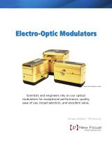
Electro-Optic Modulators Electro-Optic Modulator Family Scientists and engineers rely on our optical modulators for exceptional performance, quality, ease of use, broad selection, and excellent value. Simply Better™ Photonics
Open the catalog to page 1
Simply Better ™ Photonics New Focus Simply Better Photonics New Focus™ offers a broad line of optical modulators and drivers that are versatile, reliable and easy to use. All our optical modulators are based on the electro-optic or Pockels’ effect—the linear dependence of the index of refraction on an applied electric field. Applying a voltage across the electrodes of an electro-optic crystal changes the effective refractive index and thus the phase of light as it passes through the crystal. Our amplitude modulators span the frequency range from DC to 250 MHz while our phase modulators span an...
Open the catalog to page 2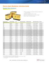
Tunable Diode Lasers Electro-Optic Modulator Selection Guide Standard Phase Modulators Phase modulators can generate frequency sidebands on Frequency range from DC to 9.2 GHz Resonant designs offer very low drive voltages Blue, Visible, and IR Wavelengths Modulator Series1 Wavelength Range Type Operating Frequency2 Modulation Depth Max Optical Intensity3 Material Standard Phase Modulators Note: All modulators are built with universal mounting options 1 More specifications available on the Newport website. Specifications are subject to change 2 Resonant modulators must be specified to a single...
Open the catalog to page 3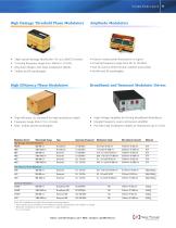
High Damage Threshold Phase Modulators Amplitude Modulators • High optical-damage thresholds—5x our LiNb03 versions • Covering frequency range from 10kHz to 2.0 GHz • Resonant designs with large modulation depths High Efficiency Phase Modulators • High efficiency (2x standard) for high modulation depth • Frequency range from 0.5 to 2.0 GHz • Blue, Visible and IR wavelengths • Used to create power fluctuations in signal • Covering frequency range from DC to 250 MHz • Can be used as electronically variable wave plates Broadband and Resonant Modulator Drivers • High-Voltage Amplifier for Driving...
Open the catalog to page 4
Simply Better ™ Photonics Phase Modulators Phase modulators are used to vary the phase of an optical beam. When driven sinusoidally, phase modulators can generate frequency sidebands on a cw optical beam. Sinusoidal phase modulation at a frequency Ω generates frequency sidebands at multiples of Ω about the central optical frequency. Given a sinusoidal phase modulation at frequency Ω and a peak phase modulation m, the phase variation is ø(t)=msin(Ωt). The electric field of the optical beam after passing through the modulator can be seen below. Left: When a phase modulator is used, the laser beam...
Open the catalog to page 5
Tunable Diode Lasers Phase and Amplitude Modulator Definitions of Characteristics Maximum Optical Intensity The maximum optical intensity of a 1-mm-diameter beam that can be passed through the crystal without causing photorefractive damage. Note that this optical damage threshold is strongly wavelength dependent. Maximum RF Power The maximum recommended RF drive power. Above this power, the electronic components will saturate or thermal effects in the crystal (such as thermal lensing) will become a problem. Maximum Vπ The voltage required to achieve a π phase shift at a given wavelength. It is...
Open the catalog to page 6All MICRO-CONTROLE / Spectra-Physics catalogs and technical brochures
 Precision Motion Control
27 Pages
 OPTICAL FIBER ALIGNMENT
6 Pages
 SA2_90028936F
1 Page
 10BPF10-370_ROHS
1 Page
 10BPF10-320_ROHS
1 Page
 10BPF10-310
1 Page
 M-401
M-4011 Page
 Tunable Diode Lasers
16 Pages
 Custom Component Solutions
6 Pages
 Vision IsoStation Brochure
5 Pages
 Nanopositioning Solutions
55 Pages
 newport ressource
1640 Pages
 Motion PL30
24 Pages
 CONEX-AG-LS25-27P
2 Pages
 Nanopositioners
40 Pages
 Prisms and retroreflectors
9 Pages
 Beamsplitters
34 Pages
 Spherical and aspherical lenses
35 Pages
 Optrical mirror
33 Pages
 Ultra-Low Loss SuperMirrors™
2 Pages
 Precision Right-Angle Prisms
1 Page
 Parallel Windows
1 Page
 Sapphire Windows
1 Page
 Compensated Attenuators
1 Page
 High-Energy Laser Beam Expanders
2 Pages
 High-Energy Variable Attenuators
3 Pages
 Laser Collimator
1 Page
 Gradient Index Micro Lenses
2 Pages
 Aspheric Condenser Lenses
1 Page
 Molded Glass Aspheric Lenses
3 Pages
 BK 7 Precision Bi-Convex Lenses
2 Pages
 Polarcor™ Linear Polarizers
1 Page
 Precision Linear Polarizers
1 Page
 Broadband Beam Samplers
1 Page
 Pellicle Beamsplitters
1 Page
 Plane Ruled Reflection Gratings
2 Pages
 Volume Bragg Gratings™
1 Page
 Ultrafast Laser Beam Sampler
1 Page
 Ultrafast Laser Chirped Mirrors
2 Pages
 Laser Diode Objective Lenses
1 Page
 Precision Objective Lenses
1 Page
 Reflective Microscope Objectives
2 Pages
 Systems Solutions brochure
6 Pages
 Polarization Controller, Manual
2 Pages
 Fiber Optic Depolarizers
1 Page
 Mode Scrambler
1 Page
 Index-Matching Fluid
1 Page
 Variable Ratio Couplers
2 Pages
 Fixed Fiber Optic Attenuator
1 Page
 Fiber Optic Switches
2 Pages
 Single Branch Fiber Bundles
1 Page
 Fiber Optic Isolator
2 Pages
 Photonic Crystal Fibers
4 Pages
 Oriel Multi-track Fiber Bundles
2 Pages
 Power Delivery Fibers
1 Page
 Liquid Light Guides
2 Pages
 Infrared Fibers
1 Page
 Fast Steering Mirrors
4 Pages
 Optical Delay Line Kit
1 Page
 Long Scan Autocorrelator
1 Page
 I-V Test Station
2 Pages
 Projects in Optics
2 Pages
 Projects in Interferometry
2 Pages
 Azimuth / Elevation Gimbals
2 Pages
 Air-Bearing System
2 Pages
 X-Ray Diffractometer
2 Pages
 Motion System
2 Pages
 LabLegs™ Upgrade Kits
1 Page
 UCS Series Cleanroom Tables
1 Page
 TE Series Table Enclosures
1 Page
 Oriel Integrating Spheres
5 Pages
 Oriel Inspection Probes
1 Page
 Oriel Focusing Lens Assembly
2 Pages
 Xenon Flashlamps
2 Pages
 Oriel InstaSpec X CCD
3 Pages
 Oriel Mini Monochromator
3 Pages
 Oriel 77200 1/4 m Monochromator
3 Pages
 OSM2 Series Spectrometers
2 Pages
 Oriel Optical Choppers
2 Pages
 Electronic Safety Shutters
1 Page
 Oriel Optical Shutter
1 Page
 Iris Diaphragms
1 Page
 X26 Series Mirror Mount
1 Page
 Mini Optical Rails and Carriers
2 Pages
 Slotted Bases
2 Pages
 SDS Series Angle Brackets
1 Page
 Rotation Adaptor
1 Page
 PBN Series Base Plates
1 Page
 Modular Riser Plates
1 Page
 Magnetic Bases
2 Pages
 Kinematic Stops and Nudgers
1 Page
 Kinematic Bases
2 Pages
 Fixed Height Platforms
1 Page
 EQ Series Angle Brackets
2 Pages
 Base Clamps
1 Page
 360 Series Angle Brackets
1 Page
 Rod Platforms
1 Page
 Rod Clamps
1 Page
 Posts and Post Holders
3 Pages
 Post Clamps and Accessories
1 Page
 Pedestal-Base Post Holders
2 Pages
 Modular Construction System
1 Page
 Holders for Pedestal Posts
1 Page
 Heavy Duty Rod Systems
2 Pages
 Dual Rod Systems
1 Page
 Breadboard Support Posts
1 Page
 Pedestal Post System
2 Pages
 Motorized Filter Wheels
1 Page
 Manual Filter Wheels
1 Page
 Indexed Filter Wheel Mounts
1 Page
 Filter Holders
1 Page
 Filter and Optic Holders
1 Page
 V-Blocks
1 Page
 Precision Beam Steerers
1 Page
 Polarizer Rotation Mounts
1 Page
 Pockels Cell Positioner
1 Page
 Kin-a-Flip Mount
1 Page
 Diffraction Grating Mount
2 Pages
 Cube Beamsplitter Holders
1 Page
 Beam Steerers
1 Page
 Aegis Qube™ Beam Routing System
5 Pages
 Variable Lens Holder
1 Page
 Self-Centering Lens Mounts
1 Page
 Multi-Axis Lens Positioners
4 Pages
 Lens Focusing Mount
1 Page
 Fixed Lens Mounts
1 Page
 Cylindrical Lens Holders
1 Page
 Compact Lens Positioners
1 Page
 Adjustable Lens Mounts
1 Page
 UV Objective Lenses
1 Page
 Objective Lenses
1 Page
 Infrared Lenses
1 Page
 Spherical Ball Micro Lenses
1 Page
 Three-Axis Spatial Filters
2 Pages
 Precision Singlet Lens Sets
3 Pages
 OptiSet™ Optics Sets
2 Pages
 Laser Beam Expanders
2 Pages
 Electronic Shutter System
1 Page
 UV Beam Viewer
1 Page
 Interferometer Flats
1 Page
 Light Pipe Homogenizer
1 Page
 VALUMAX® Right-Angle Prisms
1 Page
 VALUMAX® Broadband Mirrors
2 Pages
 Laser Line Dielectric Mirrors
2 Pages
 High-Energy Nd:YAG Laser Mirrors
2 Pages
 Broadband SuperMirrors™
1 Page
 Broadband Metallic Mirrors
2 Pages
 Broadband Dielectric Mirrors
2 Pages
 Oriel TE Cooler Controller
1 Page
 Oriel Current Preamplifier
1 Page
 Micro-Beam Profiler
1 Page
 Laser Beam Profiler
2 Pages
 High-Speed Photodetectors, GHz
7 Pages
 Oriel Silicon Detectors
2 Pages
 Oriel Pb and PbSe Detectors
2 Pages
 Oriel InGaAs and Ge Detectors
2 Pages
 Oriel Photomultiplier Tubes
2 Pages
 Fiber Optic Detectors
2 Pages
 PulseScout Autocorrelator
2 Pages
 Heat Control Filters
1 Page
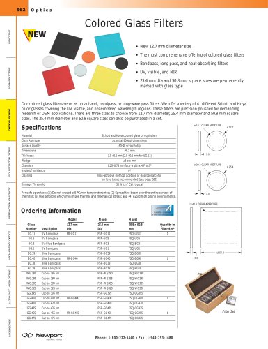 Colored Glass Filters
3 Pages
 Bandpass Filters
4 Pages
 Laser Line Filters
2 Pages
 Short and Long-Wave Pass Filters
2 Pages
 Oriel Order Sorting Filters
1 Page
 UZ Series Vertical Linear Stages
2 Pages
 HXP100 Hexapod
2 Pages
 BG Series Goniometric Cradles
4 Pages
 EL/EN Series Lab Jacks
1 Page
 ECN/ECR Series Lab Jacks
2 Pages
 Single-Mode Fiber Couplers
1 Page
 Multimode Fiber Couplers
2 Pages
 GRIN Lens Fiber Couplers
1 Page
 Fiber Optic Positioners
3 Pages
 BM Series Micrometers
2 Pages
 Apex Fiber Illuminators
2 Pages
 Series Q Deuterium Sources
1 Page
 Deuterium Lamps
2 Pages
 Apex Deuterium Lamp Sources
1 Page
 Oriel Ozone Eater
1 Page
 Ozone Blowers
1 Page
 Flange Mounted Cells
1 Page
 Beam Turning Assemblies
2 Pages
 Aspherab Lens Assemblies
2 Pages
 Mounts for Beam Probes
1 Page
 Input Hood for Light Sources
1 Page
 Holders for Oriel Single Fibers
2 Pages
 Flood Exposure Sources
6 Pages
 Mask Alignment Tools
4 Pages
 Class A Solar Simulators
3 Pages
 150 - 300 W Solar Simulators
2 Pages
 150 W Low Cost Solar Simulator
2 Pages
 Apex Monochromator Illuminators
4 Pages
 Silicon Carbide Light Source
1 Page
 Quartz Tungsten Halogen Lamps
3 Pages
 Blackbodies
2 Pages
 Apex Infrared Light Sources
2 Pages
 Xenon Flashlamp Systems
2 Pages
 Uniform Illuminators
3 Pages
 Simplicity Series Arc Sources
2 Pages
 Series Q Lamp Housings
4 Pages
 Series Q Arc Lamp Sources
2 Pages
 Oriel PhotoMax Lamp Housing
3 Pages
 Fading Test System
1 Page
 Modular Infrared Light Sources
2 Pages
 Digital Arc Lamp Power Supplies
2 Pages
 DC Short Arc Lamps
3 Pages
 Research Arc Lamp Housings
3 Pages
 Apex Arc Lamp Sources
2 Pages
 Pencil Style Calibration Lamps
3 Pages
 Calibrated Sources and Services
2 Pages
 Laser Diode Adaptors
1 Page
 Cylindrical Laser Mounts
1 Page
 Laser Diode Drivers, 500B Series
2 Pages
 TEC Controller, 300B Series
2 Pages
 VBG Raman Laser Modules
2 Pages
 Laser Diode Modules, LQN Series
2 Pages
 Alignment Laser
1 Page
 Ultraviolet Safety Equipment
1 Page
 Laser Safety Glasses and Goggles
4 Pages
 Laser Safety Windows
1 Page
 Infrared IR Viewer
1 Page
 Beam Dump
1 Page
 177 Air-Cooled Ion Lasers
2 Pages
 Empower ® Q-Switched Laser
2 Pages
 V-Xtreme™ Q-Switched Laser
2 Pages
 Fiber Pigtailed Laser Diode
1 Page
 488 nm CW Laser- Cyan™ OEM
2 Pages
 CW Lasers- Excelsior® OEM
4 Pages
 Inspire™ OPO Family
2 Pages
 Kevlar® Shears
1 Page
 Fiber Optic Scribes
1 Page
 Fiber Jacket Stripper
1 Page
 Fiber Optic Collimators
2 Pages
 Fiber Preparation Kit
1 Page
 Fiber Optic Splice
1 Page
 Fiber Coating Stripper
1 Page


Archived catalogs
 Pick & Place Machine
2 Pages
 Metrology Positioning System
2 Pages
 Adaptors and Retaining Rings
1 Page
 Mounting Bridles
1 Page


- Positioning table
- Translation stage
- Digital temperature control
- Motorized positioning table
- Temperature controller
- Precision positioning table
- Digital temperature controller
- Metal stand
- Technology positioning stage
- Automation temperature controller
- PID temperature control
- Single-axis positioning stage
- Manually-operated positioning stage
- Power meter
- 2-axis positioning table
- Compact positioning table
- PID temperature controller
- Glass lens element
- Multi-axis positioning table
- Optical filter