- Catalogs
- MICRO-CONTROLE / Spectra-Physics
- IMS-V Series High-Load Vertical Linear Stages
IMS-V Series High-Load Vertical Linear Stages

IMS-V Series High-Load Vertical Linear Stages
The document provides technical specifications for the IMS100V and IMS300V motorized linear stages. Key specifications include travel ranges of 100 mm and 300 mm, respectively, with minimum incremental motion of 0.3 µm using XPS controllers. Uni-directional repeatability is 0.2 µm, and on-axis accuracy ranges from 1.5 µm to 10 µm depending on the model. Maximum speed is 20 mm/s with up to 100 N load. The stages have a mean time between failures (MTBF) of 20,000 hours under specified conditions.
The IMS-V series features a high-load vertical linear stage design with an extruded aluminum body optimized for stiffness and minimal thermal bending. It uses four-way equal load rating ball bearings and a self-locking lead screw for stability. The drive mechanism includes a precision ground lead screw with a high-wear resistance nut, and direct position feedback is provided by a linear steel scale with 0.1 µm resolution.
The stages support a maximum load of 500 N with XPS controllers and 100 N with ESP300 or SMC100CC controllers. Compliance in pitch and yaw is specified as 0.2 µrad/N.m and 1 µrad/N.m, respectively.
Models available include IMS100V and IMS300V, with recommended motion controllers being XPS, ESP300, and SMC100CC, each supporting different payload capacities and minimum incremental motions.
Detailed dimensions for the IMS100V and IMS300V models are provided, including thread dimensions and top plate interface specifications.
Catalog excerpts
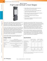
796 Phone: 1-800-222-6440 • Fax: 1-949-253-1680 M o t o r i z e d P o s i t i o n i n g MOTORIZED ROTATION MOTORIZED LINEAR STAGES TECHNICAL REFERENCE STAGES SYSTEMS CONTROLLERS AND AMPLIFIERS MOTORIZED ACTUATORS MOTORIZED OPTICAL MOUNTS Specifications IMS100V (M-IMS100V) IMS300V (M-IMS300V) Typical Guaranteed Typical Guaranteed Travel Range (mm) 100 300 Minimum Incremental Motion (ìm) 0.3 ìm with XPS, 0.6 ìm with ESP300 or SMC100CC Uni-directional Repeatability (ìm) 0.2 0.5 0.2 0.5 Reversal Value (Hysteresis) (ìm) 0.05 0.5 0.05 0.5 On-Axis Accuracy (ìm) 1.5 5 2.5 10 Maximum Speed 20 mm/s with up to 100 N load, 5 mm/s with higher loads Pitch (ìrad) 72 100 113 250 Yaw (ìrad) 32 100 75 200 MTBF 20,000 h with 300 N load and with a 10% duty cycle Weight (kg) 13.6 17 See the Motion Control Metrology Primer section (page 775) for more information on typical and guaranteed specifications IMS-V Series High-Load Vertical Linear Stages • High stiffness, FEM optimized extruded aluminum body avoids thermal bending effects • Four-way equal load rating ball bearings offer best support for high cantilevered loads • Self-locking lead screw ensures best position stability with no change of position at power off • Proprietary nut design minimizes wear and slip-stick effect • Direct position feedback provides superior accuracy and minimum hysteresis Newport’s IMS-V linear stages offer long travel vertical motion of heavy loads up to 500 N. Using the same industry-proven technology as the IMS stages, the IMS-V stages provide very high performance in a cost-effective package, making them ideal solutions for precision industrial and laboratory applications. All IMS-V series stages are optimized for maximum stability and performance using FEM analysis, resulting in a light and stable stage. While high in stiffness, the bending effect caused by different thermal expansion coefficients of the aluminum body and the steel rails is also minimized. Four-way equal load rating ball bearings provide superior support for high cantilevered loads, and the caged recirculating balls ensure maintenancefree operation without cage migration. The drive system utilizes a 16 mm diameter lead screw with a proprietary wear resistant polyethylene terephthalate nut Design Details Base Material Extruded Aluminum Bearings Four way equal loaded caged recirculating ball bearings Drive Mechanism Precision ground 16 mm diameter lead screw, High-wear resistance polyethylene terephthalate nut, no preload Drive Screw Pitch (mm) 3 Feedback Linear steel scale, 20 ìm signal period, 0.1 ìm resolution Limit Switches Optical Origin Optical, approx. 8 mm from motor side limit Motor DC servo motor UET511 Cable 5 m long motor cable included optimized for carrying high axial loads. The drive nut closely assimilates static and dynamic friction, minimizing the slip-stick effect found in classical lead screw systems. When used with our XPS motion controller, this guarantees better than 300 nm motion sensitivity, even at full load and over the life of the stage. The lead screw self locks to ensure superior in-position stability with no change of position at removal of power – something typically experienced with braked ball screw drives. Precision position feedback is supplied by a linear scale with 0.1 ìm resolution. This direct optical reading system provides superior accuracy and minimum hysteresis when compared to indirect feedback systems. The direct read system is impervious to position drift caused by motion-induced heating of the lead screw for improved accuracy and repeatability.
Open the catalog to page 1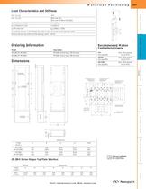
M o t o r i z e d P o s i t i o n i n g 797 Email: [email protected] • Web: newport.com TECHNICAL REFERENCE MOTORIZED LINEAR STAGES MOTORIZED ROTATION STAGES MOTORIZED OPTICAL MOUNTS MOTORIZED ACTUATORS CONTROLLERS AND AMPLIFIERS SYSTEMS Load Characteristics and Stiffness Min. -Cx; +Cx 40 N Max. -Cx; +Cx 500 N with XPS 100 N with ESP300 or SMC100CC káy, Compliance in pitch 0.2 ìrad/N.m káz, Compliance in yaw 1 ìrad/N.m Q, Off-center load QH1500N/(1 + D/90) D, Cantilever distance in mm between the center of mass of the load and the bearings center. Distance between top surface and the bearings...
Open the catalog to page 2All MICRO-CONTROLE / Spectra-Physics catalogs and technical brochures
 Precision Motion Control
27 Pages
 OPTICAL FIBER ALIGNMENT
6 Pages
 SA2_90028936F
1 Page
 10BPF10-370_ROHS
1 Page
 10BPF10-320_ROHS
1 Page
 10BPF10-310
1 Page
 M-401
M-4011 Page
 Tunable Diode Lasers
16 Pages
 Custom Component Solutions
6 Pages
 Vision IsoStation Brochure
5 Pages
 Nanopositioning Solutions
55 Pages
 newport ressource
1640 Pages
 Motion PL30
24 Pages
 CONEX-AG-LS25-27P
2 Pages
 Nanopositioners
40 Pages
 Prisms and retroreflectors
9 Pages
 Beamsplitters
34 Pages
 Spherical and aspherical lenses
35 Pages
 Optrical mirror
33 Pages
 Ultra-Low Loss SuperMirrors™
2 Pages
 Precision Right-Angle Prisms
1 Page
 Parallel Windows
1 Page
 Sapphire Windows
1 Page
 Compensated Attenuators
1 Page
 High-Energy Laser Beam Expanders
2 Pages
 High-Energy Variable Attenuators
3 Pages
 Laser Collimator
1 Page
 Gradient Index Micro Lenses
2 Pages
 Aspheric Condenser Lenses
1 Page
 Molded Glass Aspheric Lenses
3 Pages
 BK 7 Precision Bi-Convex Lenses
2 Pages
 Polarcor™ Linear Polarizers
1 Page
 Precision Linear Polarizers
1 Page
 Broadband Beam Samplers
1 Page
 Pellicle Beamsplitters
1 Page
 Plane Ruled Reflection Gratings
2 Pages
 Volume Bragg Gratings™
1 Page
 Ultrafast Laser Beam Sampler
1 Page
 Ultrafast Laser Chirped Mirrors
2 Pages
 Laser Diode Objective Lenses
1 Page
 Precision Objective Lenses
1 Page
 Reflective Microscope Objectives
2 Pages
 Systems Solutions brochure
6 Pages
 Polarization Controller, Manual
2 Pages
 Fiber Optic Depolarizers
1 Page
 Mode Scrambler
1 Page
 Index-Matching Fluid
1 Page
 Variable Ratio Couplers
2 Pages
 Fixed Fiber Optic Attenuator
1 Page
 Fiber Optic Switches
2 Pages
 Single Branch Fiber Bundles
1 Page
 Fiber Optic Isolator
2 Pages
 Photonic Crystal Fibers
4 Pages
 Oriel Multi-track Fiber Bundles
2 Pages
 Power Delivery Fibers
1 Page
 Liquid Light Guides
2 Pages
 Infrared Fibers
1 Page
 Fast Steering Mirrors
4 Pages
 Optical Delay Line Kit
1 Page
 Long Scan Autocorrelator
1 Page
 I-V Test Station
2 Pages
 Projects in Optics
2 Pages
 Projects in Interferometry
2 Pages
 Azimuth / Elevation Gimbals
2 Pages
 Air-Bearing System
2 Pages
 X-Ray Diffractometer
2 Pages
 Motion System
2 Pages
 LabLegs™ Upgrade Kits
1 Page
 UCS Series Cleanroom Tables
1 Page
 TE Series Table Enclosures
1 Page
 Oriel Integrating Spheres
5 Pages
 Oriel Inspection Probes
1 Page
 Oriel Focusing Lens Assembly
2 Pages
 Xenon Flashlamps
2 Pages
 Oriel InstaSpec X CCD
3 Pages
 Oriel Mini Monochromator
3 Pages
 Oriel 77200 1/4 m Monochromator
3 Pages
 OSM2 Series Spectrometers
2 Pages
 Oriel Optical Choppers
2 Pages
 Electronic Safety Shutters
1 Page
 Oriel Optical Shutter
1 Page
 Iris Diaphragms
1 Page
 X26 Series Mirror Mount
1 Page
 Mini Optical Rails and Carriers
2 Pages
 Slotted Bases
2 Pages
 SDS Series Angle Brackets
1 Page
 Rotation Adaptor
1 Page
 PBN Series Base Plates
1 Page
 Modular Riser Plates
1 Page
 Magnetic Bases
2 Pages
 Kinematic Stops and Nudgers
1 Page
 Kinematic Bases
2 Pages
 Fixed Height Platforms
1 Page
 EQ Series Angle Brackets
2 Pages
 Base Clamps
1 Page
 360 Series Angle Brackets
1 Page
 Rod Platforms
1 Page
 Rod Clamps
1 Page
 Posts and Post Holders
3 Pages
 Post Clamps and Accessories
1 Page
 Pedestal-Base Post Holders
2 Pages
 Modular Construction System
1 Page
 Holders for Pedestal Posts
1 Page
 Heavy Duty Rod Systems
2 Pages
 Dual Rod Systems
1 Page
 Breadboard Support Posts
1 Page
 Pedestal Post System
2 Pages
 Motorized Filter Wheels
1 Page
 Manual Filter Wheels
1 Page
 Indexed Filter Wheel Mounts
1 Page
 Filter Holders
1 Page
 Filter and Optic Holders
1 Page
 V-Blocks
1 Page
 Precision Beam Steerers
1 Page
 Polarizer Rotation Mounts
1 Page
 Pockels Cell Positioner
1 Page
 Kin-a-Flip Mount
1 Page
 Diffraction Grating Mount
2 Pages
 Cube Beamsplitter Holders
1 Page
 Beam Steerers
1 Page
 Aegis Qube™ Beam Routing System
5 Pages
 Variable Lens Holder
1 Page
 Self-Centering Lens Mounts
1 Page
 Multi-Axis Lens Positioners
4 Pages
 Lens Focusing Mount
1 Page
 Fixed Lens Mounts
1 Page
 Cylindrical Lens Holders
1 Page
 Compact Lens Positioners
1 Page
 Adjustable Lens Mounts
1 Page
 UV Objective Lenses
1 Page
 Objective Lenses
1 Page
 Infrared Lenses
1 Page
 Spherical Ball Micro Lenses
1 Page
 Three-Axis Spatial Filters
2 Pages
 Precision Singlet Lens Sets
3 Pages
 OptiSet™ Optics Sets
2 Pages
 Laser Beam Expanders
2 Pages
 Electronic Shutter System
1 Page
 UV Beam Viewer
1 Page
 Interferometer Flats
1 Page
 Light Pipe Homogenizer
1 Page
 VALUMAX® Right-Angle Prisms
1 Page
 VALUMAX® Broadband Mirrors
2 Pages
 Laser Line Dielectric Mirrors
2 Pages
 High-Energy Nd:YAG Laser Mirrors
2 Pages
 Broadband SuperMirrors™
1 Page
 Broadband Metallic Mirrors
2 Pages
 Broadband Dielectric Mirrors
2 Pages
 Oriel TE Cooler Controller
1 Page
 Oriel Current Preamplifier
1 Page
 Micro-Beam Profiler
1 Page
 Laser Beam Profiler
2 Pages
 High-Speed Photodetectors, GHz
7 Pages
 Oriel Silicon Detectors
2 Pages
 Oriel Pb and PbSe Detectors
2 Pages
 Oriel InGaAs and Ge Detectors
2 Pages
 Oriel Photomultiplier Tubes
2 Pages
 Fiber Optic Detectors
2 Pages
 PulseScout Autocorrelator
2 Pages
 Heat Control Filters
1 Page
 Colored Glass Filters
3 Pages
 Bandpass Filters
4 Pages
 Laser Line Filters
2 Pages
 Short and Long-Wave Pass Filters
2 Pages
 Oriel Order Sorting Filters
1 Page
 UZ Series Vertical Linear Stages
2 Pages
 HXP100 Hexapod
2 Pages
 BG Series Goniometric Cradles
4 Pages
 EL/EN Series Lab Jacks
1 Page
 ECN/ECR Series Lab Jacks
2 Pages
 Single-Mode Fiber Couplers
1 Page
 Multimode Fiber Couplers
2 Pages
 GRIN Lens Fiber Couplers
1 Page
 Fiber Optic Positioners
3 Pages
 BM Series Micrometers
2 Pages
 Apex Fiber Illuminators
2 Pages
 Series Q Deuterium Sources
1 Page
 Deuterium Lamps
2 Pages
 Apex Deuterium Lamp Sources
1 Page
 Oriel Ozone Eater
1 Page
 Ozone Blowers
1 Page
 Flange Mounted Cells
1 Page
 Beam Turning Assemblies
2 Pages
 Aspherab Lens Assemblies
2 Pages
 Mounts for Beam Probes
1 Page
 Input Hood for Light Sources
1 Page
 Holders for Oriel Single Fibers
2 Pages
 Flood Exposure Sources
6 Pages
 Mask Alignment Tools
4 Pages
 Class A Solar Simulators
3 Pages
 150 - 300 W Solar Simulators
2 Pages
 150 W Low Cost Solar Simulator
2 Pages
 Apex Monochromator Illuminators
4 Pages
 Silicon Carbide Light Source
1 Page
 Quartz Tungsten Halogen Lamps
3 Pages
 Blackbodies
2 Pages
 Apex Infrared Light Sources
2 Pages
 Xenon Flashlamp Systems
2 Pages
 Uniform Illuminators
3 Pages
 Simplicity Series Arc Sources
2 Pages
 Series Q Lamp Housings
4 Pages
 Series Q Arc Lamp Sources
2 Pages
 Oriel PhotoMax Lamp Housing
3 Pages
 Fading Test System
1 Page
 Modular Infrared Light Sources
2 Pages
 Digital Arc Lamp Power Supplies
2 Pages
 DC Short Arc Lamps
3 Pages
 Research Arc Lamp Housings
3 Pages
 Apex Arc Lamp Sources
2 Pages
 Pencil Style Calibration Lamps
3 Pages
 Calibrated Sources and Services
2 Pages
 Laser Diode Adaptors
1 Page
 Cylindrical Laser Mounts
1 Page
 Laser Diode Drivers, 500B Series
2 Pages
 TEC Controller, 300B Series
2 Pages
 VBG Raman Laser Modules
2 Pages
 Laser Diode Modules, LQN Series
2 Pages
 Alignment Laser
1 Page
 Ultraviolet Safety Equipment
1 Page
 Laser Safety Glasses and Goggles
4 Pages
 Laser Safety Windows
1 Page
 Infrared IR Viewer
1 Page
 Beam Dump
1 Page
 177 Air-Cooled Ion Lasers
2 Pages
 Empower ® Q-Switched Laser
2 Pages
 V-Xtreme™ Q-Switched Laser
2 Pages
 Fiber Pigtailed Laser Diode
1 Page
 488 nm CW Laser- Cyan™ OEM
2 Pages
 CW Lasers- Excelsior® OEM
4 Pages
 Inspire™ OPO Family
2 Pages
 Kevlar® Shears
1 Page
 Fiber Optic Scribes
1 Page
 Fiber Jacket Stripper
1 Page
 Fiber Optic Collimators
2 Pages
 Fiber Preparation Kit
1 Page
 Fiber Optic Splice
1 Page
 Fiber Coating Stripper
1 Page


Archived catalogs
 Pick & Place Machine
2 Pages
 Metrology Positioning System
2 Pages
 Adaptors and Retaining Rings
1 Page
 Mounting Bridles
1 Page


- Positioning table
- Translation stage
- Digital temperature control
- Motorized positioning table
- Temperature controller
- Precision positioning table
- Digital temperature controller
- Metal stand
- PID temperature control
- Single-axis positioning stage
- Power meter
- Manually-operated positioning stage
- Compact positioning table
- 2-axis positioning table
- PID temperature controller
- Glass lens element
- Optical filter
- Multi-axis positioning table
- Rotary positioning table
- Coupler