- Catalogs
- MICO, Incorporated
- Accumulator Charging Valves Catalog
Accumulator Charging Valves Catalog
1 /28Pages

Accumulator Charging Valves Catalog
1 /28Pages
Catalog excerpts

Innovative Braking and Controls Worldwide Accumulator Charging Valves single charging valves, dual charging valves, and load sensing charging valves Versatile, High-performance Accumulator Charging Valves MICO, Inc.
Open the catalog to page 1
This document is intended to provide general information about MICO Products. MICO, Inc. has attempted to present accurate information about MICO Products in its catalogs, brochures, and other printed materials. MICO, Inc. is not responsible for errors, inaccuracies, or inconsistencies that may exist in any catalog brochure or other printed materials or any damages arising from or related to reliance on information in them. Materials and specifications for MICO Products set forth in catalogs, brochures, and other printed materials are subject to change without notice or obligation. Refer to www.mico.com...
Open the catalog to page 2
Forestry Equipment Agricultural Equipment Heavy Construction Equipment Swing Drive Equipment Mining Equipment In-Plant & Warehouse Equipment Airport Support Vehicles MICO, Inc.
Open the catalog to page 3
Why choose MICO? MICO, Inc. designs, manufactures and markets hydraulic components, controls, and brake systems primarily for off-road markets. We have manufacturing facilities in: •• North Mankato, Minnesota U.S.A. •• Ontario, California U.S.A. •• Empalme, Sonora, Mexico Many of the world’s largest off-highway OEMs value the knowledgeable staff at MICO and work with us to make their products better. Our custom-engineered products are designed with the customer requirements as the primary driver. It is our intent to help customers build their systems with our expertise in hydraulic components,...
Open the catalog to page 4
Accumulator Charging Valve Catalog Code A C V – Product designator Seal material ACV = Accumulator Charge Valve Blank = Nitrile V = Fluorocarbon Charging rate S = One D = Two Type of actuation M = Hydro-mechanical Excess flow N = Not applicable F11 = Flow through, maximum flow rate in dekaliters/min is 11 (30 GPM) F13 = Flow through, maximum flow rate in dekaliters/min is 13 (35 GPM) F25 = Flow through, maximum flow rate in dekaliters/min is 25 (65 GPM) O11 = Power beyond, maximum flow rate in dekaliters/min is 11 (30 GPM) O13 = Power beyond, maximum flow rate in dekaliters/min is 13 (35 GPM)...
Open the catalog to page 5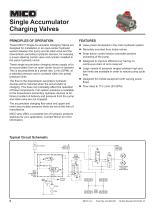
Single Accumulator Charging Valves These MICO® Single Accumulator Charging Valves are designed for installation in an open-center hydraulic system between the pump and its relief valve and the downstream secondary hydraulic devices; for example, a power steering control valve and cylinder installed in the same hydraulic circuit. These single accumulator charging valves supply oil to an accumulator from an open center circuit on demand. This is accomplished at a preset rate, L/min (GPM), at a selected pressure and is constant within the preset pressure limits. The flow to the downstream secondary...
Open the catalog to page 6
Typical Valve millimeters inches Dimensions may vary slightly by model number. SPECIFICATIONS Model Number Catalog Code (refer to page 5) Accumulator Charging Rate Tolerance High Limit Tolerance Consult MICO Applications Department for other available models and application detail. PERFORMANCE DATA System pressure. . . . . . . . . . . . . . . . . . . . . . . . . . . . . . . . . . . . . . . . . . . . . . . . . . . . . . . . . . . . . . . . . . . . . . . . . . . . . . . . . . to 206.8 bar (3000 PSI) Power beyond flow capacity . . . . . . . . . . . . . . . . . . . . . . . . . . . . . . . . . . ....
Open the catalog to page 7
Dual Accumulator Charging Valves PRINCIPLES OF OPERATION These MICO® Dual Accumulator Charging Valves perform essentially the same functions as the single charging valves. When the dual accumulator charging valves are used in a split hydraulic brake system each individual axle is separately controlled. These dual charging valves charge both accumulators. The primary advantage of dual charging valves are that if half of the brake system fails the remaining half will continue to function. zz Uses power developed in the main hydraulic system These dual charging valves charge the accumulators from...
Open the catalog to page 8
Typical Valve millimeters inches Dimensions may vary slightly by model number. SPECIFICATIONS Model Number Catalog Code (refer to page 5) Accumulator Charging Rate Tolerance High Limit Tolerance bar Consult MICO Applications Department for other available models and application detail. PERFORMANCE DATA System pressure. . . . . . . . . . . . . . . . . . . . . . . . . . . . . . . . . . . . . . . . . . . . . . . . . . . . . . . . . . . . . . . . . . . . . . . . . . . . . . . . . . to 206.8 bar (3000 PSI) Power beyond flow capacity . . . . . . . . . . . . . . . . . . . . . . . . . . . . . . . . ....
Open the catalog to page 9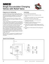
Single Accumulator Charging Valves with Relief Valve PRINCIPLES OF OPERATION The MICO® Single Accumulator Charging Valves with Relief Valve incorporate a main system relief valve. This valve was developed for installation in an open center hydraulic system between the pump and the downstream secondary hydraulic devices; for example, a power steering control valve and cylinder installed in the same hydraulic circuit. zz Incorporated pump relief valve These valves supply oil to the system accumulator from an open center circuit on demand. This is accomplished at a preset rate L/min (GPM) at a selected...
Open the catalog to page 10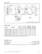
Typical Valve millimeters inches Dimensions may vary slightly by model number. SPECIFICATIONS Model Number Catalog Code (refer to page 5) Accumulator Charging Rate Tolerance High Limit Tolerance bar Relief Valve Setting Tolerance bar Consult MICO Applications Department for other available models and application detail. PERFORMANCE DATA System pressure. . . . . . . . . . . . . . . . . . . . . . . . . . . . . . . . . . . . . . . . . . . . . . . . . . . . . . . . . . . . . . . . . . . . . . . . . . . . . . . . . . to 206.8 bar (3000 PSI) Power beyond flow capacity . . . . . . . . . . . . . . ....
Open the catalog to page 11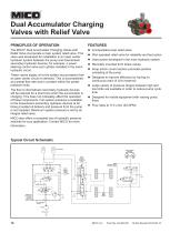
Dual Accumulator Charging Valves with Relief Valve PRINCIPLES OF OPERATION The MICO® Dual Accumulator Charging Valves with Relief Valve incorporate a main system relief valve. This valve was developed for installation in an open center hydraulic system between the pump and downstream secondary hydraulic devices; for example, a power steering control valve and cylinder installed in the same hydraulic circuit. zz Incorporated pump relief valve These valves supply oil to the system accumulators from an open center circuit on demand. This is accomplished at a preset flow rate and is constant within...
Open the catalog to page 12All MICO, Incorporated catalogs and technical brochures
 Brake Lock Application Guide
16 Pages
 MICO Product Guide
20 Pages
 Fluid Reservoirs
2 Pages
 PRESSURE LIMITER
2 Pages
 Hydraulic Brake Valves Catalog
64 Pages
 Check Valve Assembly
2 Pages
 Heavy-Duty Ratchet Handle
2 Pages
 Wireless CAN
3 Pages
 MICO CAN-bus Keypads
6 Pages
 MOBEUS
4 Pages
 CUSTOM ENGINEERED SWITCHES
48 Pages
 Load-Apportioning Valve
2 Pages
 MICO Multiple Disc Brakes
51 Pages
 Boosted Master Cylinders
27 Pages
 Air/Hydraulic Actuators
22 Pages
 Hydraulic Remote Actuators
27 Pages
 Product Guide
20 Pages
 MICO Boosted Master Cylinders
23 Pages


Archived catalogs
 Caliper Disc Brakes Catalog
23 Pages
 Electro-Hydraulic Components
15 Pages