F6
1 /41Pages

F6
1 /41Pages
Catalog excerpts
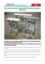
F6 F6 is a belt conveyor conceived with modular design for light load Suitable for the transportation of light product and with small dimensions, has a maximum work load of 30 Kg*. Its speed can reach 60 m/min* in function of the installed motor gear and the conveyor dimensions. F6 is a belt conveyor system, suitable for food industry and not, ideal for the transportation of products with small dimensions. F6 is an Italian product that can offer flexible solutions to a wide range of needs in the product handling process. F6 was designed to be easy to use, both by plant and machine builders and...
Open the catalog to page 2
F6 Technical Data* Product dimensions: 20÷400 mm The geometric shape of the product to be handled influences the maximum width of products accommodated by the system. Maximum weight on the conveyor: 35 Kg The maximum weight on the conveyor is limited to the need to reduce at minimum the belt wear and the stress on the tow roller Maximum conveyor length: 6 m The maximum length of the conveyor depends on the total load, the motor drive capacity, the speed and the conveyor layout. It is important to calculate and compare the maximum belt tension and the motor drive capacity in the following situations:...
Open the catalog to page 3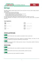
F6 Belt type MH supplies 6 different standard models of belt for some main brand in the sector: Habasit, Siegling, Ammeral, Chiorino, Mabelt. Determining factors in the choice of the belt are: - conveyor model on which it will be installed - the type of application that the conveyor belt will have to carry out - The environment in which the conveyor belt will work - Possible specifications for the brand or other requests from the client If the client requires theme, different brand, materials and accessories are available for every belt. For further information and evaluation on the best belt...
Open the catalog to page 4
F6 Standard modules Flanged end motor drive (TEF45) Belt conveyor with left/right flanged end motor drive with idle return roller Ø 45 mm Technical specifications: Standard motor Standard speed at 50 Hz (m/min) W = Belt width A = Volume depending to the motor gear type L = Conveyor length
Open the catalog to page 5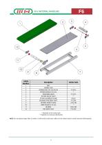
Article Number Article Code BELT SLIDING PLAN RETURN END Ø 45 mm PLATE RETURN ROLLER Ø 45 mm TENSIONING BLOCK RETURN ROLLER SHAFT PS4040 ALUMINUM FRAME FRLANGED END DRIVE PLATE BEARING INSIDE FLANGE DRIVE ROLLER Ø 45 mm BEARING END DRIVE PLATE * Depends on the motor type ** Depends on conveyor dimensions NOTE: For conveyors longer than 2 meters, it will need to add some rollers on the return track to avoid excessive belt lanyards.
Open the catalog to page 6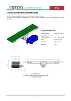
F6 Central suspended motor drive (TCP4545) Central left/right suspended motor drive with idle return rollers Ø 45 mm. The central motor drive can be installed at any point along the conveyor. and is directly connected to the belt drive roller. Technical specifications: Standard motor Standard speed at 50 Hz (m/min) W = Belt width A = Volume depending to the motor gear type L = Conveyor length
Open the catalog to page 7
Article Number BELT TENSIONING BLOCK RETURN ROLLER Ø 45 mm PS4040 ALUMINUM FRAME CENTRAL DRIVE PLATE CENTRAL DRIVE PROTECTION DRIVE SUPPORT REACTION ARM PIN REACTION LEVER DRIVE SHAFT PROTECTION DRIVE SHAFT DRIVE ROLLER RETURN ROLLER Ø 45 mm BEARING RETURN ROLLER SHAFT SLIDING PLAN * Depends on the motor type ** Depends on conveyor dimensions NOTE: For conveyors longer than 2 meters, it will need to add some rollers on the return track to avoid excessive belt lanyards.
Open the catalog to page 8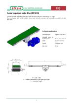
F6 Central suspended motor drive (TCP4512) Centrale left/right suspended motor drive with idle return roller Ø 45 mm and pen Ø 12 mm. The central motor drive can be installed at any point along the conveyor. and is directly connected to the belt drive roller Technical specifications: Standard motor Standard speed at 50 Hz (m/min) W = Belt width A = Volume depending to the motor gear type L = Conveyor length
Open the catalog to page 9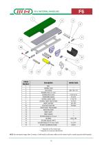
Article Number BELT SLIDING PLAN IGUS BUSH RETURN PEN Ø 12 mm RETURN PEN PLATE TENSIONING BLOCK CENTRAL DRIVE PLATE CENTRAL DRIVE PROTECTION DRIVE SUPPORT REACTION ARM PIN DRIVE SHAFT PROTECTION REACTION LEVER DRIVE SHAFT DRIVE ROLLER RETURN ROLLER Ø 45 mm BEARING RETURN ROLLER SHAFT RETURN ROLLER Ø 45 mm PLATE PS4040 ALUMINUM FRAME * Depends on the motor type ** Depends on conveyor dimensions NOTE: For conveyors longer than 2 meters, it will need to add some rollers on the return track to avoid excessive belt lanyards.
Open the catalog to page 10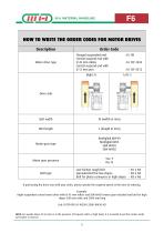
F6 HOW TO WRITE THE ORDER CODES FOR MOTOR DRIVES Description Order Code Flanged suspended end Central suspend end with Ø 45 mm rollers Central suspend end with Ø 12 mm pen Motor drive type Drive side Belt width Blet length Motor gear type Motor gear presence Belt type Low friction rough belt : N1 o N4 Spreaded belt for low slopes : N2 o N5 Belt for phase conveyors or high slopes : N3 o N6 If purchasing the drive unit with your order, please specify the required speed at the time of ordering. Example: Right suspended central motor drive with Ø 45 mm rollers and SEW WA30 motor gear included and...
Open the catalog to page 11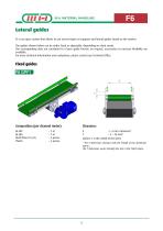
F6 Lateral guides F6 is an open system that allows to use several types of supports and lateral guides found on the market. The guides shown below can be either fixed or adjustable, depending on client needs. The corresponding data are correlated to a basic guide format: on request, accessories to increase flexibility are available. For more technical information and evaluations, please contact our Technical Office. Composition (per channel meter): X : L-3 mm minimum* Y : 3 ÷ 28 mm* (where L is the width of the belt) * The X dimension changes with the length of the aluminum spacer. The Y dimension...
Open the catalog to page 12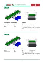
Composition (per channel meter): X : L+47 mm minimum* Y : 15 ÷ 48 mm* (where L is the width of the belt) * The X dimension changes with the length of the aluminum spacer. The Y dimension varies through the slot in the PSG95 plate. Composition (per channel meter): X : L+4 mm minimum* Y : 3 ÷25 mm* (where L is the width of the belt) * The X dimension changes with the length of the aluminum spacer. The Y dimension varies through the slot in the PSG10 plate.
Open the catalog to page 13All M.H. Material Handling S.p.A catalogs and technical brochures
 BAT L5
76 Pages
 Modul Flex
88 Pages
 MODUL-FLEX
2 Pages
 BAT-Buffer
2 Pages
 Jolly Flex
72 Pages
 F7
F741 Pages
 Dynamic mergers DU series
2 Pages
 Stacked products
7 Pages
 Spiral conveyors
1 Page
 Thermo Drive Conveyors
1 Page
 BAT F5 ENG
84 Pages
 JOLLYFLEX
72 Pages
 BIFLEX
77 Pages
 BAT-Vertical
2 Pages
 F7 Medium conveyors
2 Pages
 BAT
BAT2 Pages


- Transport rail conveyor
- Horizontal conveyor
- Conveyor for the food industry
- Roller conveyor
- Electric drive conveyor
- Inclined conveyor
- Chain conveyor
- Work conveyor
- Food conveyor
- Stainless steel conveyor
- Modular conveyor
- Bulk material conveyor
- Pallet conveyor
- Curved conveyor
- Automatic conveyor
- Conveyor for the pharmaceutical industry
- Vertical conveyor
- Crate conveyor