- Catalogs
- MG Co., Ltd.
- Temperature Controller TC10 Series
Temperature Controller TC10 Series
1 /11Pages
Temperature Controller TC10 Series
1 /11Pages
Catalog excerpts
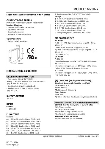
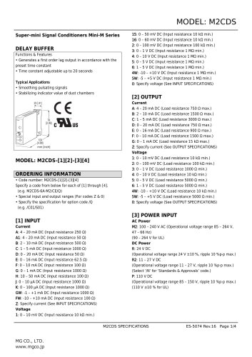
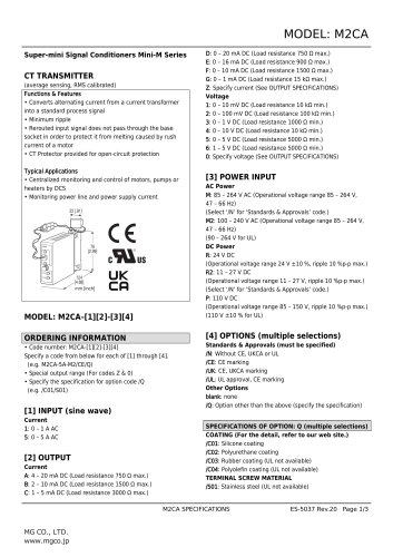
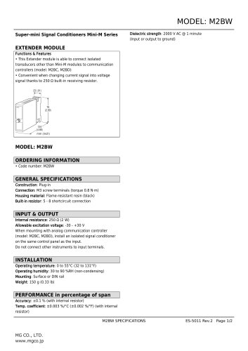
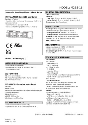
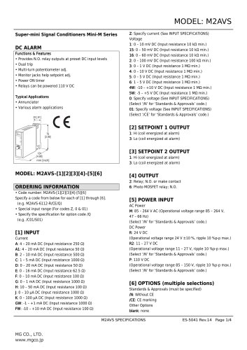
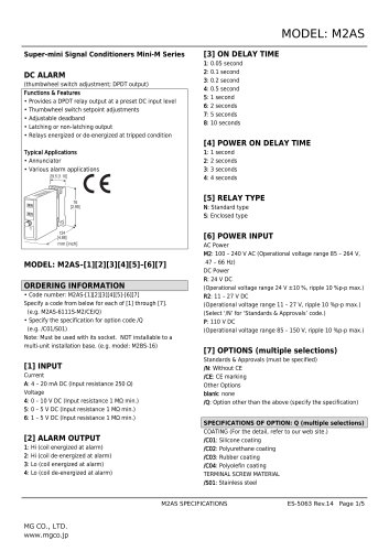
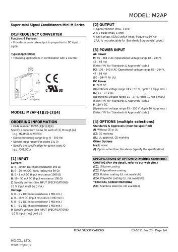
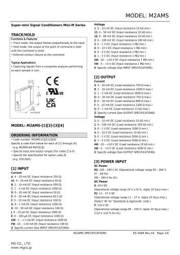
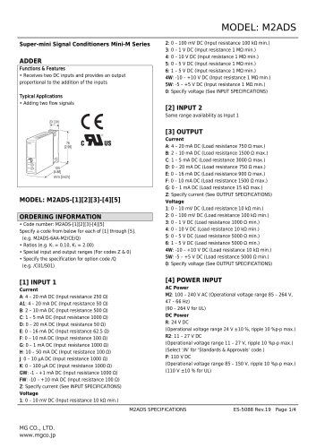
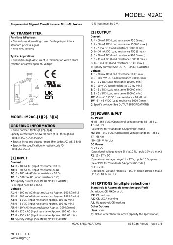
MODEL: TC10EM Temperature Controller TC10 Series TEMPERATURE CONTROLLER (Modbus, 5 digit, LED display type, size 96 x 96 mm) Functions & Features • Two PID controllers* • Universal input x 2 points, control output x 4 points, discrete input x 2 points, clamp-on current sensor input x 2 points • 2 universal inputs configurable to T/C, RTD, DC current or voltage independently • Discrete inputs usable to switch PID bank or operation mode • Control outputs configurable to MV, PV or alarm • Clamp-on current sensor input enables to detect heater wire break or over current • Auto-tuning function *Only single loop control is available while loop 1 remote SP is enabled. MODEL: TC10EM–[1]–M2 ORDERING INFORMATION • Code number: TC10EM-[1]-M2 Specify a code from below for [1]. (e.g. TC10EM-A1-M2) [1] CONTROL OUTPUT A: 0 – 20 mA DC (Load resistance 500 Ω max.) Open collector 2 points V: 0 – 10 V DC (Load resistance 2 kΩ max.) Open collector 2 points P: 12 V pulse (Load resistance 600 Ω max.) Open collector 2 points R: Relay 2 points Open collector 2 points A1: 0 – 20 mA DC (Load resistance 500 Ω max.) Auxiliary relay 2 points V1: 0 – 10 V DC (Load resistance 2 kΩ max.) Auxiliary relay 2 points P1: 12 V pulse (Load resistance 600 Ω max.) Auxiliary relay 2 points R1: Relay 2 points Auxiliary relay 2 points POWER INPUT AC Power M2: 100 – 240 V AC (Operational voltage range 85 – 264 V, 47 – 66 Hz) RELATED PRODUCTS • PC Configurator cable (model: MCN-CON or COP-US) • PC configurator software (model: TC10CFG) Downloadable at our web site. • Clamp-on current sensor (model: CLSE) (Used for detecting the heater wire break) GENERAL SPECIFICATIONS Construction: Panel flush mounting Degree of protection: IP65; applicable to the front panel of the unit with single mounting according to the specified panel cutout Configuration jack: 2.5 dia. miniature jack connector; RS-232-C level Connection: M3 separable screw terminal (torque 0.5 N·m) Solderless terminal: Refer to the drawing at the end of the section. Recommended manufacturer: Japan Solderless Terminal MFG.Co.Ltd, Nichifu Co.,ltd Applicable wire size: 0.25 to 1.65 mm2 (AWG 22 to 16) Screw terminal: Nickel-plated steel Housing material: Flame-resistant resin (black) Isolation: • Control output A, V, P, A1, V1, P1 Pv1 to Pv2 to CT1 or CT2 to Di1 or Di2 to Mv1 or Mv2 to Do1 or Do2 to Modbus to power • Control output R, R1 Pv1 to Pv2 to CT1 or CT2 to Di1 or Di2 to Mv1 to Mv2 to Do1 or Do2 to Modbus to power CT Input waveform RMS sensing: Up to 15 % of 3rd harmonic content Control mode: Standard PID, heating and cooling control (ON/OFF, PID) Proportional band (P): 0.1 to 3200.0 (temperature unit) Integral time (I): 0 to 3999 sec. Derivative time (D): 0.0 to 999.9 sec. Auto-tuning: Limit cycle method Alarm: Deviation high & low, absolute high & low, etc. Sampling cycle: 100 msec. Control cycle: 1.0 to 99.9 sec.
Open the catalog to page 1
(100 msec. fixed for Mv output 0 - 20 mA DC and 0 - 10 V DC) Mv output range: -5 - +105 % for output scale Parameters: Stored in non-volatile memory; write/erase cycle endurance: less than 1 000 000 Parameter setting: With front panel operation buttons or PC configurator software (model: TC10CFG) • Universal input • Control output • Event input Refer to the instruction manual for detail. ■Recommended solderless terminal MODBUS COMMUNICATION_ Communication: Half-duplex, asynchronous, no procedure Standard: Conforms to TIA/EIA-485-A Transmission distance: 500 meters max. Transmission media: Shielded...
Open the catalog to page 2
MODEL: TC10EM (Sensor model No.: AC input) CLSE-R5: 0 – 5 A CLSE-05: 0 – 50 A CLSE-10: 0 – 100 A CLSE-20: 0 – 200 A CLSE-40: 0 – 400 A CLSE-60: 0 – 600 A Frequency: 50 / 60 Hz (45 - 65 Hz) Max. working voltage: 480 V AC (primary side) Overload capacity: CLSE-R5: 10 A continuous, x40 (1 sec.) CLSE-05: 60 A continuous, x40 (1 sec.) CLSE-10: 120 A continuous, x40 (1 sec.) CLSE-20: 240 A continuous, x40 (1 sec.) CLSE-40: 480 A continuous, x40 (1 sec.) CLSE-60: 720 A continuous, x40 (1 sec.) Operational range CLSE-R5: ≤ 5 A CLSE-05: ≤ 50 A CLSE-10: ≤ 100 A CLSE-20: ≤ 200 A CLSE-40: ≤ 400 A CLSE-60:...
Open the catalog to page 3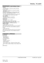
• Pv1 or Pv2: Refer to "Input type, range & conversion accuracy" section. • CT1 or CT2: ±2 % (sensor error margin not included) Cold junction compensation error (thermocouple input): CJC sensor is adjacently attached to the input terminals. CJC is available for each universal input 1 and 2. Temp. coefficient Response time Burnout response (thermocouple, RTD input): < 10 sec. Insulation resistance: > 100 MQ with 500 V DC Dielectric strength: 2000 V AC @ 1 minute (Pv1 to Pv2 to CT1 or CT2 to Di1 or Di2 to Mv1 or Mv2 to Do1 or Do2 to Modbus to power to ground) 2000 V AC @ 1 minute (Pv1 to Pv2 to...
Open the catalog to page 4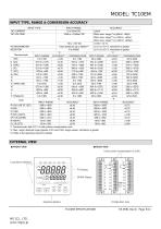
INPUT TYPE ±0.1D or ±0.1%, whichever is greater ±0.1fi or ±0.1%, whichever is greater *2. Max. range: absolute range (greater of 0% and 100% range values), whichever is greater. *3. Refer to the operating manual for details. ■ FRONT VIEW ■ REAR VIEW
Open the catalog to page 5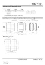
MODEL: TC10EM COMMUNICATION CABLE CONNECTIONS ■ MASTER CONNECTION TERMINATOR HOST PC TX+/RX+ TX–/RX– SG RX+ RX– *1. For using internal terminator, short-accross terminals 4 and 5. EXTERNAL DIMENSIONS & TERMINAL ASSIGNMENTS unit: mm [inch] 6 – M3 SCREW TERMINAL COVER MOUNTING BRACKET WATERTIGHT PACKING ■ PANEL CUTOUT unit: mm [inch]
Open the catalog to page 6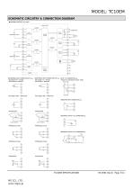
MODEL: TC10EM SCHEMATIC CIRCUITRY & CONNECTION DIAGRAM ■ CONTROL OUTPUT: A, V and P Indicator LEDs ... Isolation Comm. Circuit Control Circuit Output Circuit Output Circuit Input Circuit Display/ Setting ■ UNIVERSAL INPUT CONNECTION (Pv1) e.g. •DC Voltage (-10 – +10V DC) •DC Current (0 – 20mA DC) ■ UNIVERSAL INPUT CONNECTION (Pv2) e.g. ■ CT1 / CT2 CONNECTION e.g. •Clamp-on current Sensor (model : CLSE) Power Side k ■ DISCRETE INPUT CONNECTION e.g. Di1 comp. leadwire comp. leadwire ■ CONTROL OUTPUT 1 & 2 CONNECTION e.g. ■ CONTROL OUTPUT 3 & 4 CONNECTION e.g. Do1
Open the catalog to page 7All MG Co., Ltd. catalogs and technical brochures
 M2DNY
M2DNY3 Pages
 M2CDS
M2CDS4 Pages
 M2CA
M2CA3 Pages
 M2BW
M2BW2 Pages
 M2BS-16
5 Pages
 M2BS2
M2BS25 Pages
 M2BS-16
5 Pages
 M2BD
M2BD7 Pages
 M2BC
M2BC8 Pages
 M2AVS
M2AVS4 Pages
 M2AS
M2AS5 Pages
 M2AP
M2AP4 Pages
 M2AMS
M2AMS4 Pages
 M2ADS
M2ADS4 Pages
 M2AC
M2AC3 Pages
 CNT
CNT2 Pages
 CLSE
CLSE2 Pages
 CLSB
CLSB3 Pages
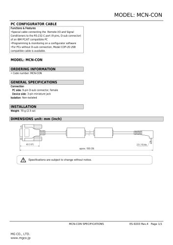 MCN-CON
1 Page
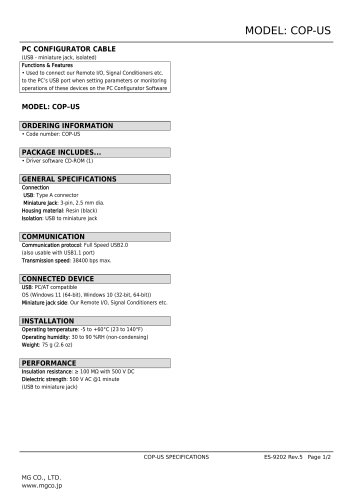 COP-US
2 Pages
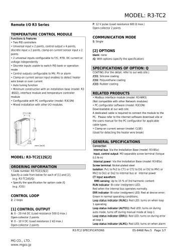 Remote I/O R3 Series
7 Pages
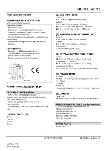 Final Control Elements
7 Pages
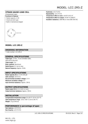 STRAIN GAUGE LOAD CELL
2 Pages
- Actuator
- Force sensor
- Linear actuator
- Electric actuator
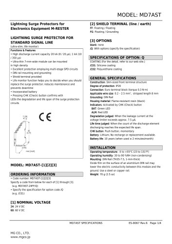
- Surge protector
- Data logger
- Tension/compression force transducer
- IO module
- Strain gauge force sensor
- Digital temperature control
- DIN rail lightning arrester
- Analog I/O
- Digital indicator
- Panel panel meter
- Signal amplifying integrated circuit
- Position transducer
- USB datalogger
- Weighing terminal
- Industrial gateway