- Catalogs
- MG Co., Ltd.
- Remote I/O R3 Series
Remote I/O R3 Series
1 /7Pages
Remote I/O R3 Series
1 /7Pages
Catalog excerpts
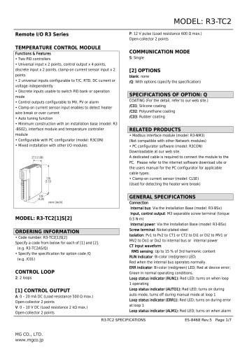
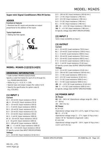
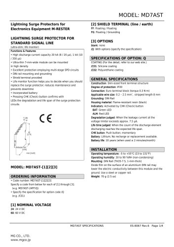
Remote I/O R3 SeriesTEMPERATURE CONTROL MODULE Functions & Features • Universal input x 2 points, control output x 4 points, discrete input x 2 points, clamp-on current sensor input x 2 points • 2 universal inputs configurable to T/C, RTD, DC current or voltage independently • Discrete inputs usable to switch PID bank or operation mode • Control outputs configurable to MV, PV or alarm • Clamp-on current sensor input enables to detect heater wire break or over current • Auto tuning function • Minimum construction with an installation base (model: R3 -BS02), interface module and temperature controller module • Configurable with PC configurator (model: R3CON) • Mixed installation with other I/O modules Specify a code from below for each of [1] and [2]. (e.g. R3-TC2AS/Q) • Specify the specification for option code /Q (e.g. /C01) A: 0 - 20 mA DC (Load resistance 500 Q max.) Open-collector 2 points V: 0 - 10 V DC (Load resistance 2 kQ max.) Open-collector 2 points P: 12 V pulse (Load resistance 600 Q max.) Open-collector 2 points blank: none /Q: With options (specify the specification) COATING (For the detail, refer to our web site.) /C01: Silicone coating /C02: Polyurethane coating /C03: Rubber coating • Modbus interface module (model: R3-NM3) (Not compatible with other Network modules) • PC configurator software (model: R3CON) A dedicated cable is required to connect the module to the PC. Please refer to the internet software download site or the users manual for the PC configurator for applicable cable types. • Clamp-on current sensor (model: CLSE) (Used for detecting the heater wire break) Internal bus: Via the Installation Base (model: R3-BSx) Input, control output: M3 separable screw terminal (torque 0.5 N'm) Internal power: Via the Installation Base (model: R3-BSx) Screw terminal: Nickel-plated steel Isolation: Pv1 to Pv2 to CT1 or CT2 to Di1 or Di2 to MV1 or MV2 to Do1 or Do2 to internal bus or internal power RMS sensing: Up to 15 % of 3rd harmonic content RUN indicator: Bi-color (red/green) LED; Red when the internal bus operates normally. ERR indicator: Bi-color (red/green) LED; Red at device error; Green in normal operating conditions. Loop status indicator (RUN1): Red LED; turns on when loop 1 operating Loop status indicator (AUTO1): Red LED; turns on during auto mode, turns off during manual mode at loop 1 Loop status indicator (ERR1): Red LED; turns on during error at loop 1 Loop status indicator (ALM1): Red LED; turns on when alarm
Open the catalog to page 1
Loop status indicator (RUN2): Red LED; turns on when loop 2 operating Loop status indicator (AUTO2): Red LED; turns on during auto mode, turns off during manual mode at loop 2 Loop status indicator (ERR2): Red LED; turns on during error at loop 2 Loop status indicator (ALM2): Red LED; turns on when alarm trip on loop 2 Control mode: Standard PID, heating and cooling control (ON/OFF, PID) Proportional band (P): 0.1 to 999.9 (temperature unit) Integral time (I): 0.0 to 9999.9 sec. Auto-tuning: Limit cycle method Alarm: Deviation high & low, absolute high & low, etc. Sampling cycle: 100 msec. Parameters:...
Open the catalog to page 2
Operating temperature: -10 to +55°C (14 to 131°F) Operating humidity: 30 to 90 %RH (non-condensing) Atmosphere: No corrosive gas or heavy dust Mounting: Installation Base (model: R3-BSx) • Pv1 or Pv2: Refer to "Input type, range & conversion accuracy" section. • CT1 or CT2: ±2 % (sensor error margin not included) • MV1 or MV2: ±0.5 % (added to the input accuracy) Cold junction compensation error: Temp. coefficient Response time Insulation resistance: > 100 MQ with 500 V DC Dielectric strength: 1000 V AC @1 minute (Pv1 to Pv2 to CT1 or CT2 to Di1 or Di2 to MV1 or MV2 to Do1 or Do2 to internal...
Open the catalog to page 3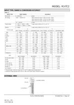
INPUT RANGE When maximum range*2 is 50 mV or less: ±20gV When maximum range*2 is 120 mV or less: ±40gV When maximum range*2 exceeds 120 mV: ±200gV 0 - 4000fi Larger value of either ±0.1 fi or ±0.1 % *1. Thermocouple: CJC error margin (2.0 °C, 3.6 °F) added value indicated above. *2. Maximum range: Absolute value of 0% or 100% of the input range, whichever is greater. EXTERNAL VIEW Loop Status Indicator
Open the catalog to page 4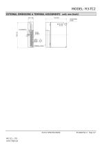
MODEL: R3-TC2 EXTERNAL DIMENSIONS & TERMINAL ASSIGNMENTS unit: mm [inch] 27.5 (1.08) TERMINAL COVER
Open the catalog to page 5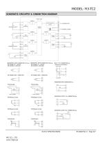
MODEL: R3-TC2 SCHEMATIC CIRCUITRY & CONNECTION DIAGRAM Indicator LEDs ... Isolation Communication Circuit Control Circuit Output Circuit INTERNAL POWER Input Circuit ■ UNIVERSAL INPUT CONNECTION (Pv1) e.g. •DC Voltage (-10 – +10V DC) •DC Current (0 – 20mA DC) + ■ UNIVERSAL INPUT CONNECTION (Pv2) e.g. •DC Voltage (-10 – +10V DC) •DC Current (0 – 20mA DC) + 11 ■ CT 1 / CT 2 CONNECTION e.g. •Clamp-on current Sensor Power Side k Load Side ■ DISCRETE INPUT CONNECTION e.g. •Thermocouple comp. leadwire 14 ■ CONTROL OUTPUT 1 & 2 CONNECTION e.g. ■ CONTROL OUTPUT 3 & 4 CONNECTION e.g.
Open the catalog to page 6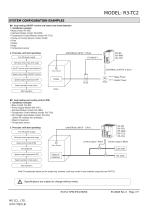
MODEL: R3-TC2 SYSTEM CONFIGURATION EXAMPLES ■ 1 loop heating ON/OFF control and heater wire break detection 1. Installation example: • Base (model: R3–BS) • Interface Module (model: R3–NM3) • Temperature Control Module (model: R3–TC2) • Clamp-on Current Sensor (model: CLSE) • Oven • Heater • Relay • Temperature sensor 2. Proccess until start operating: Turn ON power supply Set input sensor type and range Set CT input to wire break detection Temp. Sensor Select control mode (ON/OFF Control) Specify target temperature (SP) Relay Power Heater Power Select operation mode (auto) Oven Start operation...
Open the catalog to page 7All MG Co., Ltd. catalogs and technical brochures


- Actuator
- Force sensor
- Linear actuator
- Electric actuator
- Surge protector
- Data logger
- Tension/compression force transducer
- Strain gauge force sensor
- Digital temperature control
- DIN rail lightning arrester
- Analog I/O
- Digital indicator
- Panel panel meter
- Position transducer
- Signal amplifying integrated circuit
- USB datalogger
- Weighing terminal
- Industrial gateway