- Catalogs
- MG Co., Ltd.
- M2BS-16
M2BS-16
1 /5Pages
M2BS-16
1 /5Pages
Catalog excerpts
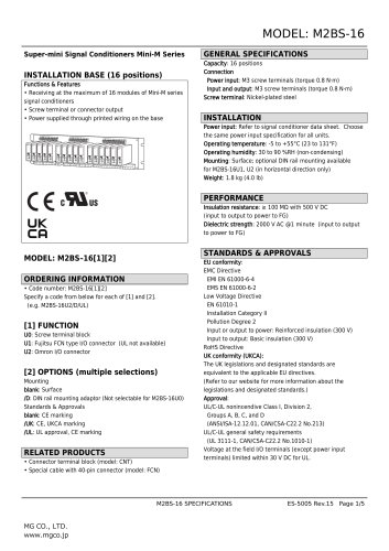
Super-mini Signal Conditioners Mini-M Series INSTALLATION BASE (16 positions) Functions & Features • Receiving at the maximum of 16 modules of Mini-M series signal conditioners • Screw terminal or connector output • Power supplied through printed wiring on the base GENERAL SPECIFICATIONS_ Power input: M3 screw terminals (torque 0.8 N'iri) Input and output: M3 screw terminals (torque 0.8 N'iri) Screw terminal: Nickel-plated steel Power input: Refer to signal conditioner data sheet. Choose the same power input specification for all units. Operating humidity: 30 to 90 %RH (non-condensing) Mounting: Surface; optional DIN rail mounting available for M2BS-16U1, U2 (in horizontal direction only) Insulation resistance: > 100 MO with 500 V DC (input to output to power to FG) Dielectric strength: 2000 V AC @1 minute (input to output to power to FG) ORDERING INFORMATION_ Specify a code from below for each of [1] and [2]. (e.g. M2BS-16U2/D/UL) U0: Screw terminal block U1: Fujitsu FCN type I/O connector (UL not available) U2: Omron I/O connector [2] OPTIONS (multiple selections) Mounting blank: Surface /D: DIN rail mounting adaptor (Not selectable for M2BS-16U0) Standards & Approvals RELATED PRODUCTS_ • Connector terminal block (model: CNT) • Special cable with 40-pin connector (model: FCN) STANDARDS & APPROVALS_ EMC Directive EMI EN 61000-6-4 EMS EN 61000-6-2 Low Voltage Directive EN 61010-1 Installation Category II Pollution Degree 2 Input or output to power: Reinforced insulation (300 V) Input to output: Basic insulation (300 V) RoHS Directive The UK legislations and designated standards are equivalent to the applicable EU directives. (Refer to our website for more information about the legislations and designated standards.) UL/C-UL nonincendive Class I, Division 2, UL/C-UL general safety requirements (UL 3111-1, CAN/CSA-C22.2 No.1010-1) Voltage at the field I/O terminals (except power input terminals) limited within 30 V DC for UL.
Open the catalog to page 1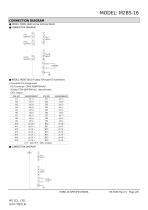
MODEL: M2BS-16 CONNECTION DIAGRAM ■ MODEL: M2BS-16U0 (screw terminal block) ■ CONNECTION DIAGRAM 9 Ch.1 OUTPUT 12 ■ MODEL: M2BS-16U1 (Fujitsu FCN type I/O connector) • Connector Pin Assignment
Open the catalog to page 2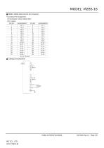
MODEL: M2BS-16 ■ MODEL: M2BS-16U2 (Omron I/O connector) • Connector Pin Assignment
Open the catalog to page 3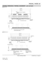
*165 (6.50) required for pneumatic tubing for M2PV. **Attached to M2CA and M2CE.
Open the catalog to page 4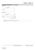
MODEL: M2BS-16 MOUNTING REQUIREMENTS unit: mm [inch] ■ M2BS-16U0 460 [18.11] *Installed in horizontal direction only. Specifications are subject to change without notice.
Open the catalog to page 5All MG Co., Ltd. catalogs and technical brochures
 M2DNY
M2DNY3 Pages
 M2CDS
M2CDS4 Pages
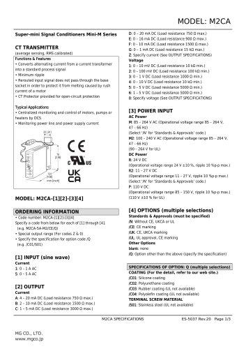 M2CA
M2CA3 Pages
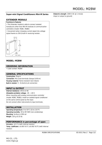 M2BW
M2BW2 Pages
 M2BS-16
5 Pages
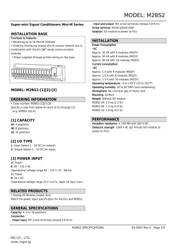 M2BS2
M2BS25 Pages
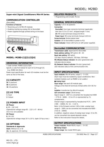 M2BD
M2BD7 Pages
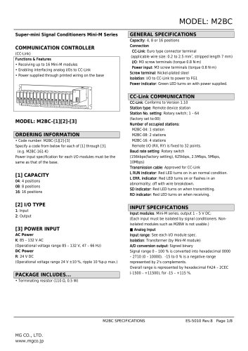 M2BC
M2BC8 Pages
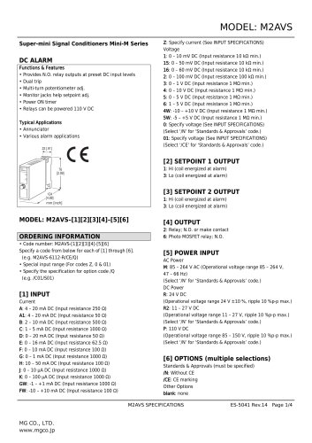 M2AVS
M2AVS4 Pages
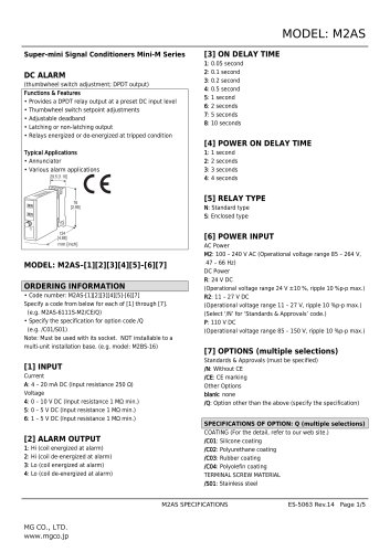 M2AS
M2AS5 Pages
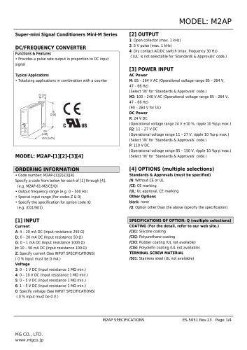 M2AP
M2AP4 Pages
 M2AMS
M2AMS4 Pages
 M2ADS
M2ADS4 Pages
 M2AC
M2AC3 Pages
 CNT
CNT2 Pages
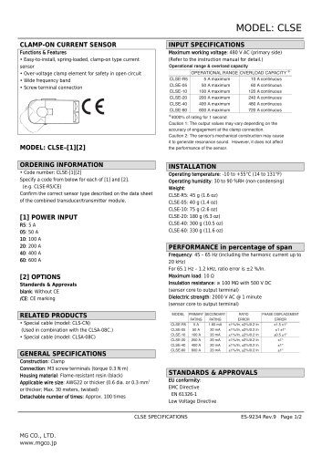 CLSE
CLSE2 Pages
 CLSB
CLSB3 Pages
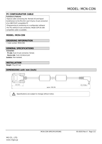 MCN-CON
1 Page
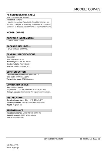 COP-US
2 Pages
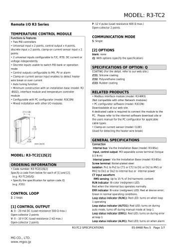 Remote I/O R3 Series
7 Pages
 Final Control Elements
7 Pages
 STRAIN GAUGE LOAD CELL
2 Pages
- Actuator
- Force sensor
- Linear actuator
- Electric actuator
- Surge protector
- Data logger
- Tension/compression force transducer
- IO module
- Strain gauge force sensor
- Digital temperature control
- DIN rail lightning arrester
- Analog I/O
- Digital indicator
- Panel panel meter
- Signal amplifying integrated circuit
- Position transducer
- USB datalogger
- Temperature controller
- Weighing terminal
- Industrial gateway