M2BC
1 /8Pages
M2BC
1 /8Pages
Catalog excerpts
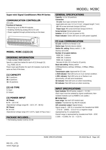
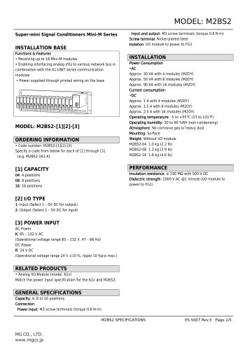
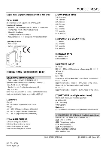
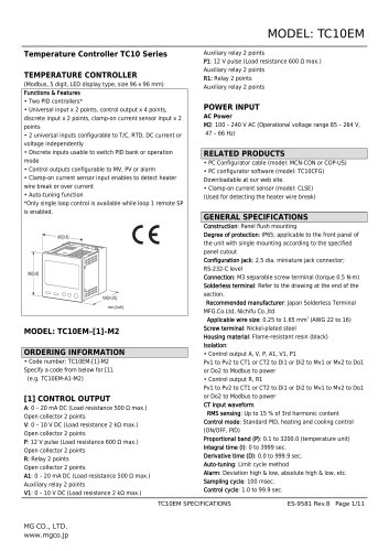
MODEL: M2BC Super-mini Signal Conditioners Mini-M Series COMMUNICATION CONTROLLER (CC-Link) Functions & Features • Receiving up to 16 Mini-M modules • Enabling interfacing analog I/Os to CC-Link • Power supplied through printed wiring on the base MODEL: M2BC–[1][2]-[3] ORDERING INFORMATION • Code number: M2BC-[1][2]-[3] Specify a code from below for each of [1] through [3]. (e.g. M2BC-161-K) Power input specification for each I/O modules must be the same as that of the base. CC-Link: Conforms to Version 1.10 Station type: Remote device station Station No. setting: Rotary switch; 1 – 64 (factory set to:00) Number of occupied stations: M2BC-04: 1 station M2BC-08: 2 stations M2BC-16: 4 stations Remote I/O (RX, RY) is fixed to 32 points. Baud rate setting: Rotary switch (156kbps(factory setting), 625kbps, 2.5Mbps, 5Mbps, 10Mbps) Transmission cable: Approved for CC-Link L RUN indicator: Red LED turns on in an normal condition. L ERR. indicator: Red LED turns on or flashes in an abnormality; off with wire breakdown. SD indicator: Red LED turns on when transmitting. RD indicator: Red LED turns on when receiving. INPUT SPECIFICATIONS [3] POWER INPUT AC Power K: 85 – 132 V AC (Operational voltage range 85 – 132 V, 47 – 66 Hz) DC Power R: 24 V DC (Operational voltage range 24 V ±10 %, ripple 10 %p-p max.) PACKAGE INCLUDES... Capacity: 4, 8 or 16 positions Connection CC-Link: Euro type connector terminal (applicable wire size: 0.2 to 2.5 mm2, stripped length 7 mm) I/O: M3 screw terminals (torque 0.8 N·m) Power input: M3 screw terminals (torque 0.8 N·m) Screw terminal: Nickel-plated steel Isolation: I/O to CC-Link to power to FG1 Power indicator: Green LED turns on with power supplied. CC-Link COMMUNICATION GENERAL SPECIFICATIONS Input modules: Mini-M series; output 1 – 5 V DC; (Each input must be isolated by signal conditioners. Nonisolated modules such as M2BW is not usable.) ■ Analog Input Input range: See each I/O module spec. Isolation: Transformer (by Mini-M module) A/D conversion output: Signed binary Signal range 0 – 100 % is converted into hexadecimal 0000 – 2710 (0 – 10000). -15 to 0 % is a negative range represented by 2's complements. Overall range is represented by hexadecimal FA24 – 2CEC (-1500 – +11500), for -15 – +115 %.
Open the catalog to page 1
RWr n+0 through RWr n+3 for 4 inputs. RWr n+0 through RWr n+7 for 8 inputs. RWr n+0 through RWr n+15 for 16 inputs. OUTPUT SPECIFICATIONS_ Output modules: Model M2VS; input 1 - 5 V DC ■ Analog Output Output range: See model M2VS spec. Isolation: Transformer D/A conversion output: Signed binary Signal range 0 - 100 % is converted into hexadecimal 0000 Overall range is represented by hexadecimal FA24 - 2CEC (-1500 - +11500), for -15 - +115 %. Power Consumption: approx. 6 VA without I/O module approx. 30 VA with 4 modules (M2DY) approx. 50 VA with 8 modules (M2DY) approx. 90 VA with 16 modules (M2DY)...
Open the catalog to page 2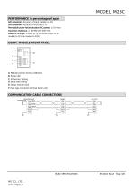
MODEL: M2BC PERFORMANCE in percentage of span A/D conversion: Accuracy of input module ±0.1% D/A conversion: Accuracy of M2VS ±0.1 % Permissible power failure duration (AC power): ≤ 10 msec. Insulation resistance: ≥ 100 MΩ with 500 V DC Dielectric strength: 1000 V AC @ 1 minute (power to I/O module to CC-Link module to FG1) COMM. MODULE FRONT PANEL PU-2 A: Modular jack for factory calibration B: Power LED C: Station No. Setting D: Baud rate Setting E: Status indicator LED F: Euro type connector terminal for CC-Link COMMUNICATION CABLE CONNECTIONS MASTER UNIT TERMINATOR blue white yellow
Open the catalog to page 3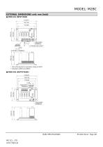
EXTERNAL DIMENSIONS unit: mm [inch] ■ M2BC-041 (INPUT BASE) * 165 [6.50] required for pneumatic tubing for M2PV. ** Attached to M2CA and M2CE.
Open the catalog to page 4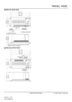
* 165 [6.50] required for pneumatic tubing for M2PV. ** Attached to M2CA and M2CE.
Open the catalog to page 5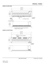
H- * 165 [6.50] required for pneumatic tubing for M2PV. ** Attached to M2CA and M2CE.
Open the catalog to page 6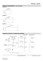
MODEL: M2BC MOUNTING REQUIREMENTS unit: mm [inch] ■ M2BC-04 190 [7.48] SCHEMATIC CIRCUITRY & CONNECTION DIAGRAM ■ INPUT BASE COMMUNICATION MODULE To Other CC-Link Devices I/O CPU Modular Jack for Factory Calibration MODULAR JACK SERIAL TRANSMISSION LINE
Open the catalog to page 7
MODEL: M2BC Specifications are subject to change without notice.
Open the catalog to page 8All MG Co., Ltd. catalogs and technical brochures
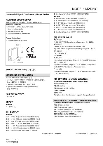 M2DNY
M2DNY3 Pages
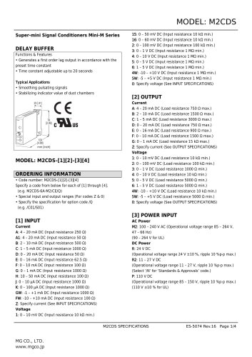 M2CDS
M2CDS4 Pages
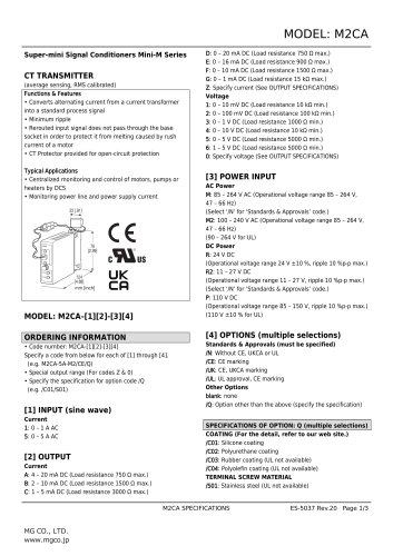 M2CA
M2CA3 Pages
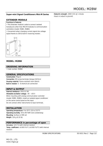 M2BW
M2BW2 Pages
 M2BS-16
5 Pages
 M2BS2
M2BS25 Pages
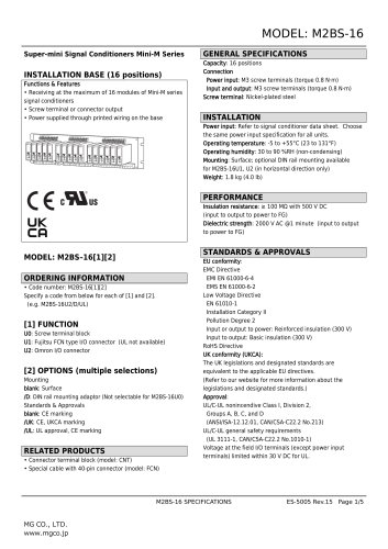 M2BS-16
5 Pages
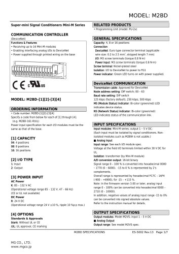 M2BD
M2BD7 Pages
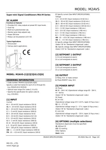 M2AVS
M2AVS4 Pages
 M2AS
M2AS5 Pages
 M2AP
M2AP4 Pages
 M2AMS
M2AMS4 Pages
 M2ADS
M2ADS4 Pages
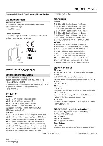 M2AC
M2AC3 Pages
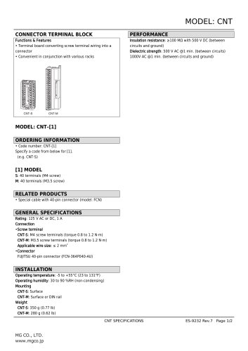 CNT
CNT2 Pages
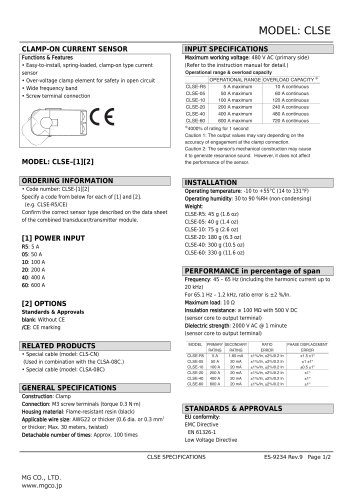 CLSE
CLSE2 Pages
 CLSB
CLSB3 Pages
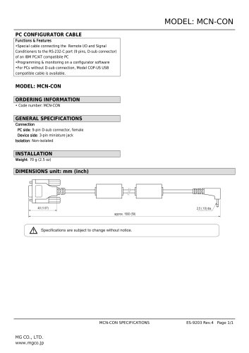 MCN-CON
1 Page
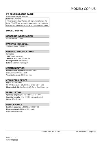 COP-US
2 Pages
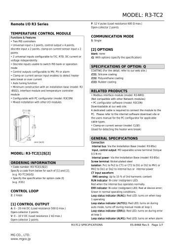 Remote I/O R3 Series
7 Pages
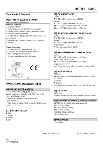 Final Control Elements
7 Pages
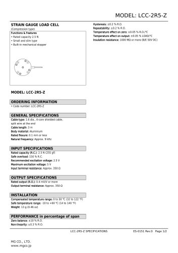 STRAIN GAUGE LOAD CELL
2 Pages
- Actuator
- Force sensor
- Linear actuator
- Electric actuator
- Surge protector
- Data logger
- Tension/compression force transducer
- Strain gauge force sensor
- Digital temperature control
- DIN rail lightning arrester
- Analog I/O
- Digital indicator
- Panel panel meter
- Position transducer
- Signal amplifying integrated circuit
- USB datalogger
- Temperature controller
- Weighing terminal
- Industrial gateway