- Catalogs
- MG Co., Ltd.
- M2AVS
M2AVS
1 /4Pages
M2AVS
1 /4Pages
Catalog excerpts

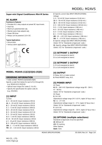
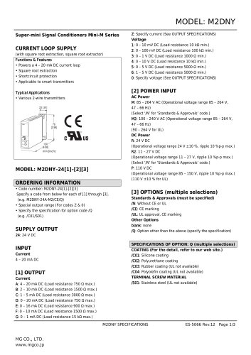
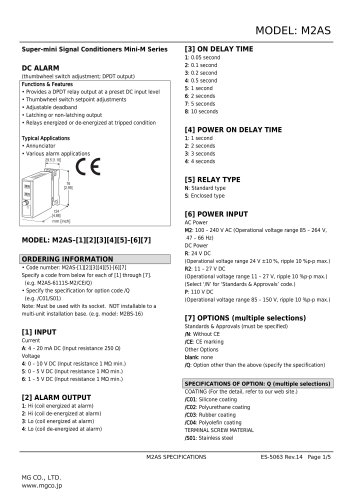
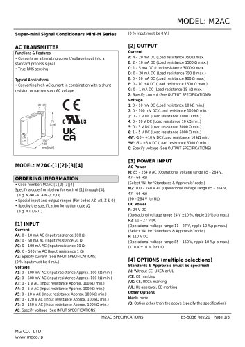
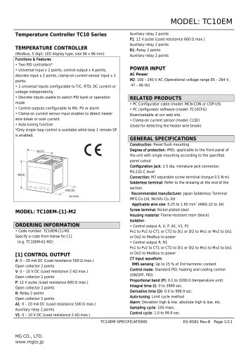
MODEL: M2AVS Super-mini Signal Conditioners Mini-M Series DC ALARM Functions & Features • Provides N.O. relay outputs at preset DC input levels • Dual trip • Multi-turn potentiometer adj. • Monitor jacks help setpoint adj. • Power ON timer • Relays can be powered 110 V DC Typical Applications • Annunciator • Various alarm applications 23 [.91] Z: Specify current (See INPUT SPECIFICATIONS) Voltage 1: 0 – 10 mV DC (Input resistance 10 kΩ min.) 15: 0 – 50 mV DC (Input resistance 10 kΩ min.) 16: 0 – 60 mV DC (Input resistance 10 kΩ min.) 2: 0 – 100 mV DC (Input resistance 100 kΩ min.) 3: 0 – 1 V DC (Input resistance 1 MΩ min.) 4: 0 – 10 V DC (Input resistance 1 MΩ min.) 5: 0 – 5 V DC (Input resistance 1 MΩ min.) 6: 1 – 5 V DC (Input resistance 1 MΩ min.) 4W: -10 – +10 V DC (Input resistance 1 MΩ min.) 5W: -5 – +5 V DC (Input resistance 1 MΩ min.) 0: Specify voltage (See INPUT SPECIFICATIONS) (Select ‘/N’ for ‘Standards & Approvals’ code.) 01: Specify voltage (See INPUT SPECIFICATIONS) (Select ‘/CE’ for ‘Standards & Approvals’ code.) [2] SETPOINT 1 OUTPUT Model 1: Hi (coil energized at alarm) 3: Lo (coil energized at alarm) 1: Hi (coil energized at alarm) 3: Lo (coil energized at alarm) 2: Relay; N.O. or make contact 6: Photo MOSFET relay; N.O. ORDERING INFORMATION • Code number: M2AVS-[1][2][3][4]-[5][6] Specify a code from below for each of [1] through [6]. (e.g. M2AVS-6112-R/CE/Q) • Special input range (For codes Z, 0 & 01) • Specify the specification for option code /Q (e.g. /C01/S01) [1] INPUT Current A: 4 – 20 mA DC (Input resistance 250 Ω) A1: 4 – 20 mA DC (Input resistance 50 Ω) B: 2 – 10 mA DC (Input resistance 500 Ω) C: 1 – 5 mA DC (Input resistance 1000 Ω) D: 0 – 20 mA DC (Input resistance 50 Ω) E: 0 – 16 mA DC (Input resistance 62.5 Ω) F: 0 – 10 mA DC (Input resistance 100 Ω) G: 0 – 1 mA DC (Input resistance 1000 Ω) H: 10 – 50 mA DC (Input resistance 100 Ω) J: 0 – 10 μA DC (Input resistance 1000 Ω) K: 0 – 100 μA DC (Input resistance 1000 Ω) GW: -1 – +1 mA DC (Input resistance 1000 Ω) FW: -10 – +10 mA DC (Input resistance 100 Ω) [5] POWER INPUT AC Power M: 85 – 264 V AC (Operational voltage range 85 – 264 V, 47 – 66 Hz) (Select ‘/N’ for ‘Standards & Approvals’ code.) DC Power R: 24 V DC (Operational voltage range 24 V ±10 %, ripple 10 %p-p max.) R2: 11 – 27 V DC (Operational voltage range 11 – 27 V, ripple 10 %p-p max.) (Select ‘/N’ for ‘Standards & Approvals’ code.) P: 110 V DC (Operational voltage range 85 – 150 V, ripple 10 %p-p max.) (Select ‘/N’ for ‘Standards & Approvals’ code.) [6] OPTIONS (multiple selections) Standards & Approvals (
Open the catalog to page 1
MODEL: M2AVS /Q: Option other than the above (specify the specification) SPECIFICATIONS OF OPTION: Q (multiple selections) COATING (For the detail, refer to our web site.) /C01: Silicone coating /C02: Polyurethane coating /C03: Rubber coating /C04: Polyolefin coating TERMINAL SCREW MATERIAL /S01: Stainless steel Mechanical life: 5 × 10⁷ cycles For maximum relay life with inductive loads, external protection is recommended. ■ Photo MOSFET Relay Maximum switching voltage: 30 V AC or 50 V DC Maximum switching current: 0.5 A ON resistance: ≤ 2 kΩ Leakage current at OFF: ≤ 10 μA For maximum relay...
Open the catalog to page 2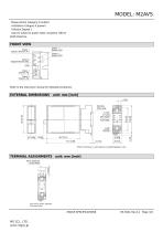
MODEL: M2AVS Measurement Category II (output) Installation Category II (power) Pollution Degree 2 Input to output to power: Basic insulation (300 V) RoHS Directive FRONT VIEW Output 1 Monitor LED Output 1 Setpoint Monitor (A1) Output 2 Monitor LED Output 2 Setpoint Monitor (A2) COM Output 1 Setpoint Adj. Output 2 Setpoint Adj. Refer to the instruction manual for detailed procedures. EXTERNAL DIMENSIONS unit: mm [inch] 6 [.23] DIN RAIL 35mm wide • When mounting, no extra space is needed between units. TERMINAL ASSIGNMENTS unit: mm [inch] INPUT RESISTOR (model: REM2) Input shunt resistor attached...
Open the catalog to page 3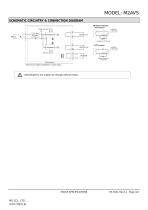
MODEL: M2AVS SCHEMATIC CIRCUITRY & CONNECTION DIAGRAM ■ Relay Protection • AC Powered COM. SP ADJ. Inductive Load (Coil) • DC Powered Inductive Load (Coil) Diode, Varistor or CR Circuit Base Socket *Input shunt resistor attached for current input. Specifications are subject to change without notice.
Open the catalog to page 4All MG Co., Ltd. catalogs and technical brochures
 M2DNY
M2DNY3 Pages
 M2CDS
M2CDS4 Pages
 M2CA
M2CA3 Pages
 M2BW
M2BW2 Pages
 M2BS-16
5 Pages
 M2BS2
M2BS25 Pages
 M2BS-16
5 Pages
 M2BD
M2BD7 Pages
 M2BC
M2BC8 Pages
 M2AS
M2AS5 Pages
 M2AP
M2AP4 Pages
 M2AMS
M2AMS4 Pages
 M2ADS
M2ADS4 Pages
 M2AC
M2AC3 Pages
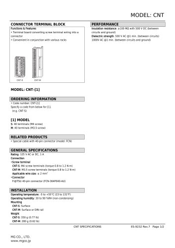 CNT
CNT2 Pages
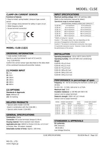 CLSE
CLSE2 Pages
 CLSB
CLSB3 Pages
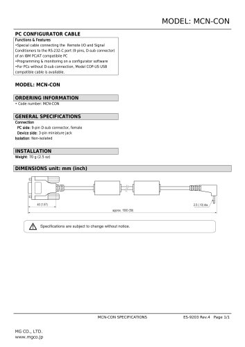 MCN-CON
1 Page
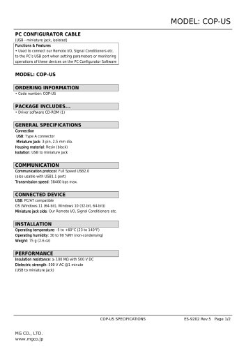 COP-US
2 Pages
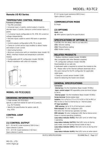 Remote I/O R3 Series
7 Pages
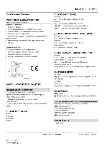 Final Control Elements
7 Pages
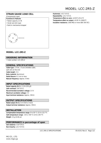 STRAIN GAUGE LOAD CELL
2 Pages
- Actuator
- Force sensor
- Linear actuator
- Electric actuator
- Surge protector
- Data logger
- Tension/compression force transducer
- IO module
- Strain gauge force sensor
- Digital temperature control
- DIN rail lightning arrester
- Analog I/O
- Digital indicator
- Panel panel meter
- Position transducer
- Signal amplifying integrated circuit
- USB datalogger
- Temperature controller
- Weighing terminal
- Industrial gateway