- Catalogs
- MG Co., Ltd.
- Final Control Elements
Final Control Elements
1 /7Pages
Final Control Elements
1 /7Pages
Catalog excerpts
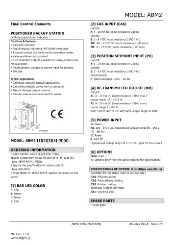
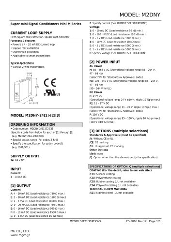
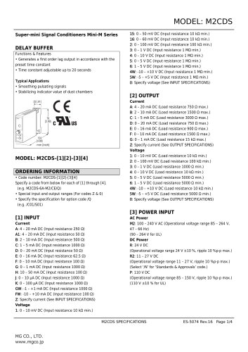
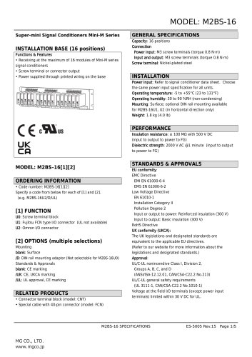
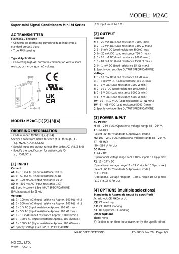
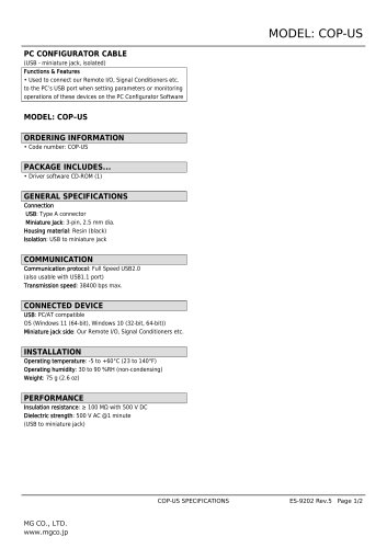
MODEL: ABM2 Final Control Elements POSITIONER BACKUP STATION (with bargraph/digital indicator) Functions & Features • Bargraph indicator • Digital display indicating PV/CAS/MV selectable • External contact closure to switch operation modes • Valve positioner incorporated • Re-transmitted outputs available for valve position and manual status • Potentiometer, voltage or current input for setpoint • DIN size Typical Applications • Computer and DCS backup applications • Controlling electric valves from a computer • Manual damper position control • Remote manual control of electric valves [3] POSITION SETPOINT INPUT (PV) Current A: 4 – 20 mA DC (Input resistance 250 Ω) Voltage 6: 1 – 5 V DC (Input resistance 1 MΩ min.) Potentiometer R: Total resistance 100 Ω – 10 kΩ [4] RE-TRANSMITTED OUTPUT (MV) Current A1: 4 – 20 mA DC (Load resistance 350 Ω max.) output range -15 - +115 % A2: 4 – 20 mA DC (Load resistance 350 Ω max.) output range 0 - 100 % Note: Select '/A2' to use with same output range as ABM. Current A: 4 – 20 mA DC (Input resistance 250 Ω) Voltage 6: 1 – 5 V DC (Input resistance 1 MΩ min.) 4W: -10 – +10 V DC (Input resistance 1 MΩ min.) 5W: -5 – +5 V DC (Input resistance 1 MΩ min.) AC Power M2: 100 – 240 V AC (Operational voltage range 85 – 264 V, 47 – 66 Hz) DC Power R: 24 V DC (Operational voltage range 24 V ±10 %, ripple 10 %p-p max.) MODEL: ABM2-[1][2][3][4]-[5][6] ORDERING INFORMATION • Code number: ABM2-[1][2][3][4]-[5][6] Specify a code from below for each of [1] through [6]. (e.g. ABM2-RAAA1-M2/Q) • Specify the specification for option code /Q (e.g. /C01/S01) • Scale (Refer to 'SCALE PLATE' section for details on the scale.) [1] BAR LED COLOR R: Red Y: Amber G: Green B: Blue [6] OPTIONS blank: none /Q: Options other than the above (specify the specification) SPECIFICATIONS OF OPTION: Q (multiple selections) COATING (For the detail, refer to our web site.) /C01: Silicone coating /C02: Polyurethane coating /C03: Rubber coating TERMINAL SCREW MATERIAL /S01: Stainless steel SPARE PARTS • Scale plate
Open the catalog to page 1
Construction: Panel flush mounting Degree of protection: IP65; applicable to the front panel for single unit mounted according to the specified panel cutout Connection: M3 separable screw terminal (torque 0.6 N'iri) Solderless terminal: Refer to the drawing at the end of the Recommended manufacturer: Japan Solderless Terminal MFG. Co., Ltd., Nichifu Co., Ltd. (Solderless terminals with insulation sleeve do not fit.) Applicable wire size: 0.25 to 1.65 mm2 Screw terminal: Nickel-plated steel (standard) or stainless steel Housing material: Flame-resistant resin (gray) Manual output switching: With...
Open the catalog to page 2
■ Remote output switching: External contact closure switches the ABM2 to MAN mode when the CAS-MAN selector is at CAS position (Not switched with MAN position. Refer to the table 1) Sensing (open): Approx. 4.5 V DC ON voltage: < 1 V DC ON resistance: < 10 kQ OFF voltage: > 2.6 V DC OFF resistance: > 49.9 kQ OUTPUT SPECIFICATIONS_ MV output Conformance range: Rated load: 240 V AC or 30 V DC @ 1 A (resistive load) For maximum relay life with inductive loads, external protection is recommended. Mechanical life: 5 x 10⁷ cycles Maximum switching voltage: 250 V AC or 125 V DC (0.2 A) (resistive load)...
Open the catalog to page 3
SCALE PLATE■ WHAT MUST BE SPECIFIED WHEN ORDERING Following two methods can specify scale plate. a) Using ‘Scale Plate Designer' Access 'Design Scale Plate' in the our web site. Scale plate can be designed in this web site. By function below, it can be easy to create standard design or original design. [Design Automatically] Entering Minimum, Maximum, and Unit allows to create automatically a scale plate. Maximum created scale division number is ’43.9’. [Specify Division Interval] Division Interval can be specified according to the application. [Specify Division Number] It is available to create...
Open the catalog to page 4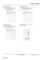
• Type 3: 2.0 Scale Span < 2.6 Number of divisions: 32 to 41.9 Scale: Starts at 0, increments in 0.05 / 0.5 / 5 / 50 / 500. Min. and max. values are indicated. 4 digits including negative sign and decimal point. Division lines: Long, Short, Medium, Short, Medium, Short, Medium, Short, Long (8 divisions repeating) • Type 5: 5.5 Scale Span < 11.0 Number of divisions: 22 to 43.9 Scale: Starts at 0, increments in 0.01 / 0.1 / 1 / 10 / 100 / 1000. Min. and max. values are indi-cated. 4 digits including negative sign and decimal point. Division lines: Long, Medium, Medium, Medium, Long (4 divisions...
Open the catalog to page 5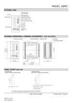
MODEL: ABM2 EXTERNAL VIEW CAS Output LED (ON at CAS Mode) Tag Plate MAN Output LED (ON at Manual Mode) Bargraph Display MAN Control Button (UP) MAN Control Button (DOWN) Digital Display MV/DZ LED INF. LED Digital Display Selector EXTERNAL DIMENSIONS & TERMINAL ASSIGNMENTS unit: mm [inch] WATERTIGHT PACKING MOUNTING BRACKET TERMINAL COVER 4–M3 SCREW 20–M3 SCREW TERMINAL PANEL CUTOUT unit: mm • Single Mounting (Conform to degree of protection IP65) • Clustered Mounting (Not conform to degree of protection IP65) • When mounting, no extra space is needed between units. Panel thickness: 1.6 – 8.0...
Open the catalog to page 6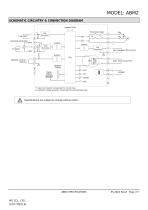
MODEL: ABM2 SCHEMATIC CIRCUITRY & CONNECTION DIAGRAM Indicator LEDs • • • Positioning Output REMOTE OUTPUT SWITCH Digital Display *1. Input shunt resistor incorporated for current input. *2. Excitation voltage generator incorporated for potentiometer input. Specifications are subject to change without notice.
Open the catalog to page 7All MG Co., Ltd. catalogs and technical brochures


- Actuator
- Force sensor
- Linear actuator
- Electric actuator
- Surge protector
- Data logger
- Tension/compression force transducer
- IO module
- Strain gauge force sensor
- Digital temperature control
- DIN rail lightning arrester
- Analog I/O
- Panel panel meter
- Position transducer
- Signal amplifying integrated circuit
- USB datalogger
- Temperature controller
- Weighing terminal
- Industrial gateway