Catalog excerpts

Magnetic precision has a name MagVector™ MV2 3-Axis Magnetic Sensor Datasheet Version 2.5 (Revision 1.0) June 2020
Open the catalog to page 1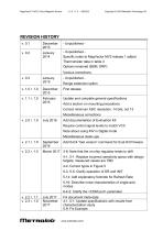
MagVector™ MV2 3-Axis Magnetic Sensor Copyright © 2020 Metrolab Technology SA - Unpublished Specific notes to MagVector MV2 release 1 added Thermometer data in table 4 Options renamed (BSM, DRP) Various corrections First release Update and complete general specifications Range extension option Add a section on mounting precautions Correct minimum ADC resolution: 14 bits, not 13 Miscellaneous corrections Add documentation of Evaluation Kit Require control signal levels to match VCC Note about using INV in Digital mode Miscellaneous clean-ups Add 0xC4 “Get version” command for Eval Kit...
Open the catalog to page 2
MagVector™ MV2 3-Axis Magnetic Sensor Copyright © 2020 Metrolab Technology SA 5-10: Fix description of data output format 4-1, 5-1: Add performance characteristics for VCC=5 V Indicate that the CS and D-A signals are active-low Insert block diagram corresponding to pin-out Update build instructions for MV2 Evaluation Kit software Miscellaneous clarifications
Open the catalog to page 3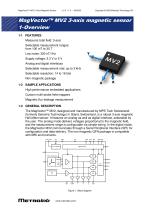
MagVector™ MV2 3-Axis Magnetic Sensor Copyright © 2020 Metrolab Technology SA MagVector™ MV2 3-axis magnetic sensor 1- Overview 1-1 FEATURES Measures total field: 3-axis Selectable measurement ranges: from 100 mT to 30 T Low noise: 300 nT/√Hz Supply voltage: 3.3 V or 5 V Analog and digital interfaces Selectable measurement rate: up to 3 kHz Selectable resolution: 14 to 16 bits Non-magnetic package 1-2 SAMPLE APPLICATIONS High performance embedded applications Custom multi-probe field mappers Magnetic flux leakage measurement 1-3 GENERAL DESCRIPTION The MagVector™ MV2, designed and...
Open the catalog to page 4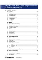
MagVector™ MV2 3-Axis Magnetic Sensor Copyright © 2020 Metrolab Technology SA MagVector™ MV2 3-axis magnetic sensor 2- Document contents 2-1 TABLE OF CONTENTS 1- Overview 4- Analog Mode Operation 5- Digital Mode Operation
Open the catalog to page 5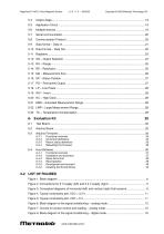
MagVector™ MV2 3-Axis Magnetic Sensor Copyright © 2020 Metrolab Technology SA Functional overview Command definitions Return status definitions Rebuilding the firmware Functional overview Installation and execution Setup file format Recompilation Development environment Installing the libxml2 library
Open the catalog to page 6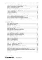
MagVector™ MV2 3-Axis Magnetic Sensor Copyright © 2020 Metrolab Technology SA
Open the catalog to page 7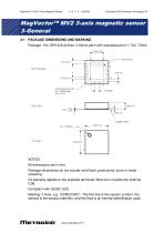
MagVector™ MV2 3-Axis Magnetic Sensor Copyright © 2020 Metrolab Technology SA MagVector™ MV2 3-axis magnetic sensor 3- General 3-1 PACKAGE DIMENSIONS AND MARKING Package: 16L QFN 3x3x0.9mm, 0.50mm pitch with exposed pad of 1.70x1.70mm NOTES: All dimensions are in mm. Package dimensions do not include mold flash, protrusions, burrs or metal smearing. Co-planarity applies to the exposed terminals. Maximum co-planarity shall be 0.08. Compliant with JEDEC-220. Marking: 3 lines, e.g. “03/MV2/5AC”. The first line is the version number, the second is the product identifier, and the third is an...
Open the catalog to page 8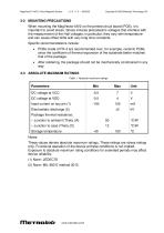
MagVector™ MV2 3-Axis Magnetic Sensor Copyright © 2020 Metrolab Technology SA 3-2 MOUNTING PRECAUTIONS When mounting the MagVector MV2 on the printed circuit board (PCB), it is important to avoid stress. Stress induces piezoelectric voltages that interfere with the measurement of the Hall voltages; in particular, they vary with temperature and can cause offset drifts with very long time constants. Specific recommendations include: • PCBs made of FR-4 are recommended over, for example, ceramic PCBs, since the coefficient of thermal expansion of the substrate better matches that of the...
Open the catalog to page 9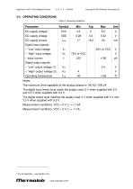
MagVector™ MV2 3-Axis Magnetic Sensor Copyright © 2020 Metrolab Technology SA 3-4 OPERATING CONDITIONS Table 2. Operating conditions Digital input signals: – “Low” input voltage – “High” input voltage – Input current Digital output signals: – “Low” output voltage (1) – “High” output voltage (2) Operating temperature Notes: The maximum drive capability of the analog outputs is 100 kΩ / 500 pF. The digital input levels must match the supply used: 5 V when supplied with 5 V and 3.3 V when supplied with 3.3 V. The digital output level matches the supply used: 5 V when supplied with 5 V and 3.3...
Open the catalog to page 10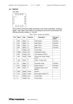
MagVector™ MV2 3-Axis Magnetic Sensor Copyright © 2020 Metrolab Technology SA The functions of the pins differ according to the mode of operation, analog or digital – see Table 3 and Table 4. Unused pins can be left unconnected; the internal pull-down resistor is ~100 kΩ. Table 3. Pinout – analog mode operation Z-axis output Temperature output Internal core supply voltage (3.3 V) Digital - Analog mode Output inversion Extended Measurement Range Main supply voltage (5 V) Y-axis output X-axis output
Open the catalog to page 11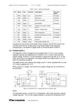
MagVector™ MV2 3-Axis Magnetic Sensor Copyright © 2020 Metrolab Technology SA Table 4. Pinout – digital mode operation Serial MISO Serial Chip Select Serial MOSI Internal core supply voltage (3.3 V) Digital - Analog mode Analog mode output inversion Data ready Main supply voltage (5 V) Unused pins may be left unconnected. Note, however, that the INV control line, normally used only for Analog mode, also affects Digital mode operation; consequently, if connected in Digital mode, it should be tied to LOGIC 0. 3-6 POWER SUPPLY The MagVector MV2 is designed to be supplied with 5 V. An on-chip...
Open the catalog to page 12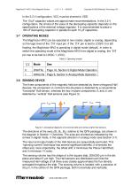
MagVector™ MV2 3-Axis Magnetic Sensor Copyright © 2020 Metrolab Technology SA In the 3.3 V configuration, VCC must be shorted to VDD. The 10 µF capacitor values are approximate recommendations. In the 3.3 V configuration, the choice of the value of the decoupling capacitor depends on the specifications of the external voltage regulator. It is recommended to place a 100 nF decoupling capacitor in parallel to each 10 µF capacitors. 3-7 OPERATING MODES The MagVector MV2 can be operated in two modes: digital or analog, depending on the logic level of the D-A input pin. If the D-A pin is tied to...
Open the catalog to page 13

