


Application note: Grounding and lightning protection tests with MI 3155

Application note: Grounding and lightning protection tests with MI 3155
Catalog excerpts

Application Note Earthing and lightning protection tests with MI 3155 A hospital is generally a complex of buildings huddled together, often evolved rather than planned. Constructing, maintaining and testing grounding protection in such an environment is a worthy challenge. The system is complex and filled with redundancy, designed for power reliability and safety of the users. Lightning protection and earthing systems Hospital as a complex is generally a TT earthing system when viewed from the outside. They often have internal transformer substation where earthing for the whole complex is constructed. This system has a particularly low earth impedance. The solution is simpler for earthing electrode maintenance and earth resistance measurements. On the other hand, each building could have its own connection to earth. This can lower interference through earth for sensitive instruments, but it also has higher resistance and makes maintenance more complex with many locations to cover. Courtyards and other open spaces have to be kept on an equalized potential to prevent step voltage hazard in case of a large fault or a lightning strike. Earth electrode should be a wide underground device like a loop, mesh or a plane with multiple parallel connections to it. There should be a lattice of conductors throughout the foundations with its own way to earth, keeping the base potential of each building constant. The ground electrode is usually a loop or a mesh and covers most of the area under the building. Lightning protection design depends on the roof of the buildings’ and grounds shape. Inside, the critical rooms must have full Faraday cage protection both to limit the disturbances and to keep them safe from overvoltage. Machines like MRI are very
Open the catalog to page 1
sensitive to electromagnetic radiation that other devices, like RTG, can produce. Designer has to keep that in mind. Operating theatres have their own insulated networks that need to be grounded as a whole. Lightning strike is a very extreme case for the installation. There is no absolutely guaranteed protection, only some measures that can help limit the damage. System of heavy conductors leading directly to the ground is the main one, but it cannot prevent voltages inducing anywhere in the installation or side flashes from one conductor to the other. Similar effects can be caused by lightning...
Open the catalog to page 2
electrode would be 100 m and to C electrode 200 m from the electrical centre of the object, which is not always known. In urban areas, it is not common to have this much space available. 2 clamps method Methods with clamps are much quicker and easier to perform. They do not require disconnecting the earth electrode or special instruments, only a current clamp and a current generator. Current is injected into the earthing leg as close to the electrode as possible. A voltage-inducing clamp can be used, or any kind of connector that can be applied to the wire without disconnecting it. The measurement...
Open the catalog to page 3
2-clamp method A pair of clamps is also a part of the standard set for MI 3155. They are mainly different in connectors: A 1018 has integrated test wire for connection to the instrument, and A 1019 has connectors for standard test leads. The only settable parameter is maximum acceptable resistance for pass/fail indication. The measurement is entirely automatic, and it is not important which clamp comes top or bottom. Use the threewire test lead and insert it into the test connector on the top of the instrument. Connect the banana connectors one on top of the other and insert into the clamp. Use...
Open the catalog to page 4All METREL catalogs and technical brochures
 MI 3136 EurotestCOMBO XC EN
4 Pages
 MI 2992 Power Analyser ENG
6 Pages
 SW 1406 Metrel Cloud App
1 Page
 MI 3116 PV AnalyserXA
2 Pages
 A 1732 DC EVSE Adapter EN
2 Pages
 MI 3340 AlphaEE XA EN
6 Pages
 MI 3211 TeraOhmHP 10 kV EN
2 Pages
 MI 3215 TeraOhmHP 15 kV EN
2 Pages
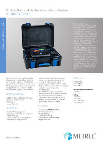 MI 3114 PV Tester EN
2 Pages
 MI 3115 PV Analyser EN
2 Pages
 MI 3132 EV Tester EN
3 Pages
 MI 3365 OmegaEE XD EN
8 Pages
 MI 3365 M OmegaEE XD EN
8 Pages
 MI 3365 F OmegaEE XD EN
8 Pages
 MI 3365 25A OmegaEE XD EN
8 Pages
 MI 3360 OmegaGT XA guide EN
56 Pages
 MD 9210 Mini Clamp Meter EN
2 Pages
 MD 9930 Thermal camera EN
2 Pages
 Medical Facilities catalogue
64 Pages
 Building Facilities catalogue
72 Pages
 General catalogue 2023 EN
272 Pages
 MI 3299 HV demo BOX
1 Page
 SW 1203 Metrel SDK EN
3 Pages
 MI 3360 OmegaGT XA EN
4 Pages
 MI 3325 MultiServicerXD EN
4 Pages
 MI 3394 CE MultiTesterXS EN
2 Pages
 MI 3394 CE MultiTesterXA EN
3 Pages
 MI 6601 MediTest EN
4 Pages
 MI 3110 EurotestIM EN
2 Pages
 A 1722 PRCD adapter EN
2 Pages
 A 1632 eMobility Analyser EN
2 Pages
 A 1532 XA EVSE adapter EN
2 Pages
 A 1532 EVSE adapter EN
2 Pages
 MI 2093 Line Tracer EN
2 Pages
 MI 3109 EurotestPV Lite EN
2 Pages
 MI 3108 EurotestPV EN
2 Pages
 MI 3125 BT EurotestCOMBO EN
2 Pages
 MI 3125 EurotestCOMBO EN
2 Pages
 MI 3100 SE EurotestEASI EN
2 Pages
 MI 3102 BT EurotestXE EN
2 Pages
 MI 3143 Euro Z 440 V EN
2 Pages
 MI 3144 Euro Z 800 V EN
2 Pages
 MI 3202 GigaOhm 5 kV EN
2 Pages
 MI 3201 TeraOhm 5 kV Plus EN
2 Pages
 MI 3311 GammaGT EN
2 Pages
 MI 3309 BT DeltaGT EN
2 Pages
 MI 3242 MicroOhm 2A EN
2 Pages
 MI 3250 MicroOhm 10A EN
2 Pages
 MI 3252 MicroOhm 100A EN
2 Pages
 MI 3281 WR Analyser EN
2 Pages
 MI 2891 Power Simulator EN
2 Pages
 MI 2883 Energy Master EN
4 Pages
 MI 2885 Master Q4 EN
4 Pages
 MI 2884 Energy Master XA EN
4 Pages
 MI 2892 Power Master EN
4 Pages
 MI 2893 Power Master XT EN
4 Pages
 MI 3205 TeraOhmXA 5kV EN
2 Pages
 MI 3210 TeraOhm XA 10kV EN
2 Pages
 MI 3290 Earth Analyser EN
4 Pages
 MI 3280 DT Analyser EN
2 Pages
 MI 3209 TeraOhmLT 10kV EN
2 Pages
 MI 3152 EurotestXC EN
2 Pages
 Metrel application catalogue
28 Pages
 MI 3155 EurotestXD EN
4 Pages
 MI 3102 BT EurotestXE
2 Pages


- Digital imager
- Industrial camera module
- Automation software solution
- Management software solution
- Monitoring analyzer
- Analysis software solution
- Infrared imager
- Process software
- Automatic analyser
- METREL Windows software
- Calibration system
- Cloud-based software
- Control software
- USB camera module
- METREL portable tester
- Monitoring software solution
- Portable analyzer
- METREL measurement software
- METREL digital tester
- Thermographic camera