


Application note: Earth resistance measurement and 62 percent rule

Application note: Earth resistance measurement and 62 percent rule
The document outlines a rule from IEEE 81-2012 Annex C, which is based on a simplified model of rods with specific preconditions: the current through both rods (E and H) is the same, the soil is uniform, and the electrodes are hemispherical. If the distance between E and H is sufficient, they can be treated as hemispherical electrodes.
Earth Resistance Measurement and the 62% Rule:
The 62% rule is a well-known guideline in earth resistance measurements using the Fall of Potential (FoP) method. It states that the measurement S probe should be placed at 61.8% of the distance between the center E of the tested earthing system and the auxiliary test probe H.
Application Note:
For earth resistance measurements on objects with auxiliary grounding, such as transmission towers, the condition IE = IH is not met. In such cases, the earthing current IE must be measured separately using the method described in IEEE 81-2012 Ch. 8.2.2.6, implemented in the MI 3290 Earth Analyser.
Graphical Presentation and Measurement Adjustments:
During measurements, both probes E and H conduct current, causing a ground potential rise (GPR) around the electrodes, depicted as a funnel. The GPR of one probe affects the other, leading to measurement errors. The 62% method helps mitigate this by ensuring the voltage between E and S (62%) reflects the GPR of the E probe without H probe influence.
Correction Formula and Coefficient:
The formula for distance between E and S must be adjusted with a coefficient ki, resulting in shorter distances. The document provides a table of typical ki values and corresponding distances as a percentage of D. For example, if ki = 0.4, the S probe should be positioned at 46% of the distance between E and H.
Conclusion:
The document provides detailed guidelines and adjustments for accurate earth resistance measurements, emphasizing the importance of the 62% rule and the need for corrections based on specific conditions.
Catalog excerpts

Application Note Earth resistance measurement and the 62% rule Everybody, who is familiar with the earth resistance measurements knows the 62 % rule: The rule (recommendation) is defined in IEEE 81-2012 in Annex C. It is based on simplified model of rods and some additional preconditions: - Current trough both rods (E and H) is the same: IE = IH - Uniform soil - Hemispherical electrodes If the distance between E and H rode is big enough, then the rods can be treated as hemispherical electrodes. If the soil can be treated as uniform soil then the following equations are valid: The distance between the E and S is calculated out of the following equation (C.9 in IEEE 81): 1 1 (D-x) D When performing the earth resistance measurement with the Fall of Potential (FoP) method you have to put the measurement S probe on a distance of 61,8% of the distance between the centre E of the tested earthing system and the auxiliary test probe H. The positive root of equation is the location of the S probe x0 = dE_S=0.618 D The S probe must be located on the straight line between E and H probe.
Open the catalog to page 1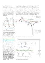
During the measurement both probes E and H conduct a current therefore the potential around the electrodes raises (GPR – ground potential raise). The graphical presentation of this potential raise around the probe has a form of a funnel (Figure 2). is influenced by the GPR of the other probe. When performing the measurements of the potential raise around the probe only the summary of both GRP can be measured. Therefore simple measurement of the voltage between E probe and zero ground results in an error and one of the possible solution is to use the 62% method. Within this method and the above...
Open the catalog to page 2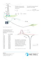
Therefore the formula Eq.1 must be corrected with the coefficient ki: ki = This results in shorter distances between E and S probe: Figure 4: 4 flex clamp method Some typical values of ki and corresponding distances dE_S between E and S are listed in the table below: ki METREL D.D. Measuring and Regulation Equipment Manufacturer Ljubljanska 77, SI-1354 Horjul, Slovenia T +386 (0)1 75 58 200, F +386 (0)1 75 49 226 [email protected], www.metrel.si 46% 62% For example, if ki = 0,4 then the S probe must be positioned on 46% of the distance between E and H probe. The funnel around the auxiliary H probe...
Open the catalog to page 3All METREL catalogs and technical brochures
 MI 3136 EurotestCOMBO XC EN
4 Pages
 MI 2992 Power Analyser ENG
6 Pages
 SW 1406 Metrel Cloud App
1 Page
 MI 3116 PV AnalyserXA
2 Pages
 A 1732 DC EVSE Adapter EN
2 Pages
 MI 3340 AlphaEE XA EN
6 Pages
 MI 3211 TeraOhmHP 10 kV EN
2 Pages
 MI 3215 TeraOhmHP 15 kV EN
2 Pages
 MI 3114 PV Tester EN
2 Pages
 MI 3115 PV Analyser EN
2 Pages
 MI 3132 EV Tester EN
3 Pages
 MI 3365 OmegaEE XD EN
8 Pages
 MI 3365 M OmegaEE XD EN
8 Pages
 MI 3365 F OmegaEE XD EN
8 Pages
 MI 3365 25A OmegaEE XD EN
8 Pages
 MI 3360 OmegaGT XA guide EN
56 Pages
 MD 9210 Mini Clamp Meter EN
2 Pages
 MD 9930 Thermal camera EN
2 Pages
 Medical Facilities catalogue
64 Pages
 Building Facilities catalogue
72 Pages
 General catalogue 2023 EN
272 Pages
 MI 3299 HV demo BOX
1 Page
 SW 1203 Metrel SDK EN
3 Pages
 MI 3360 OmegaGT XA EN
4 Pages
 MI 3325 MultiServicerXD EN
4 Pages
 MI 3394 CE MultiTesterXS EN
2 Pages
 MI 3394 CE MultiTesterXA EN
3 Pages
 MI 6601 MediTest EN
4 Pages
 MI 3110 EurotestIM EN
2 Pages
 A 1722 PRCD adapter EN
2 Pages
 A 1632 eMobility Analyser EN
2 Pages
 A 1532 XA EVSE adapter EN
2 Pages
 A 1532 EVSE adapter EN
2 Pages
 MI 2093 Line Tracer EN
2 Pages
 MI 3109 EurotestPV Lite EN
2 Pages
 MI 3108 EurotestPV EN
2 Pages
 MI 3125 BT EurotestCOMBO EN
2 Pages
 MI 3125 EurotestCOMBO EN
2 Pages
 MI 3100 SE EurotestEASI EN
2 Pages
 MI 3102 BT EurotestXE EN
2 Pages
 MI 3143 Euro Z 440 V EN
2 Pages
 MI 3144 Euro Z 800 V EN
2 Pages
 MI 3202 GigaOhm 5 kV EN
2 Pages
 MI 3201 TeraOhm 5 kV Plus EN
2 Pages
 MI 3311 GammaGT EN
2 Pages
 MI 3309 BT DeltaGT EN
2 Pages
 MI 3242 MicroOhm 2A EN
2 Pages
 MI 3250 MicroOhm 10A EN
2 Pages
 MI 3252 MicroOhm 100A EN
2 Pages
 MI 3281 WR Analyser EN
2 Pages
 MI 2891 Power Simulator EN
2 Pages
 MI 2883 Energy Master EN
4 Pages
 MI 2885 Master Q4 EN
4 Pages
 MI 2884 Energy Master XA EN
4 Pages
 MI 2892 Power Master EN
4 Pages
 MI 2893 Power Master XT EN
4 Pages
 MI 3205 TeraOhmXA 5kV EN
2 Pages
 MI 3210 TeraOhm XA 10kV EN
2 Pages
 MI 3290 Earth Analyser EN
4 Pages
 MI 3280 DT Analyser EN
2 Pages
 MI 3209 TeraOhmLT 10kV EN
2 Pages
 MI 3152 EurotestXC EN
2 Pages
 Metrel application catalogue
28 Pages
 MI 3155 EurotestXD EN
4 Pages
 MI 3102 BT EurotestXE
2 Pages



- Digital imager
- Industrial camera module
- Automation software solution
- Management software solution
- Monitoring analyzer
- Analysis software solution
- Infrared imager
- Process software
- Automatic analyser
- METREL Windows software
- Calibration system
- Cloud-based software
- Control software
- USB camera module
- METREL portable tester
- Monitoring software solution
- Portable analyzer
- METREL measurement software
- METREL digital tester
- Thermographic camera