- Catalogs
- Metra Mess- und Frequenztechnik in Radebeul e.K.
- "Piezoelectric Accelerometers - Theory and Application"
"Piezoelectric Accelerometers - Theory and Application"
1 /52Pages

"Piezoelectric Accelerometers - Theory and Application"
1 /52Pages
Catalog excerpts
Manfred Weber Metra Mess- und Frequenztechnik in RadebeuI e.K. www.MMF.de Piezoelectric Accelerometers
Open the catalog to page 1
Piezoelectric Accelerometers Theory and Application Manfred Weber Metra Mess- und Frequenztechnik in Radebeul e.K. © 2012
Open the catalog to page 2
Published by: Manfred Weber Metra Mess- und Frequenztechnik in Radebeul e.K. MeiBner Str. 58 D-01445 Radebeul / Germany Phone +49-351-836 2191 © 2012 Metra Mess- und Frequenztechnik Radebeul Specifications subject to change.
Open the catalog to page 3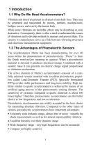
1 Introduction 1.1 Why Do We Need Accelerometers? Vibration and shock are present in all areas of our daily lives. They may be generated and transmitted by motors, turbines, machine-tools, bridges, towers, and even by the human body. While some vibrations are desirable, others may be disturbing or even destructive. Consequently, there is often a need to understand the causes of vibrations and to develop methods to measure and prevent them. The sensors we manufacture serve as a link between vibrating structures and electronic measurement equipment. 1.2 The Advantages of Piezoelectric Sensors The...
Open the catalog to page 6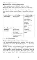
• No moving parts - no wear • Self-generating - no external power required • Great variety of models available for nearly any purpose • Integration of the output signal provides velocity and displacement The following table shows advantages and disadvantages of other common types of vibration sensors compared to piezoelectric accelerometers: 1.3 Instrumentation The piezoelectric principle requires no external energy. Only alternating acceleration can be measured. This type of accelerometer is not capable of a true DC response, e.g. gravitation acceleration. The high impedance sensor output needs...
Open the catalog to page 7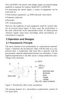
M72 and M208. For sensors with charge output, an external charge amplifier is required, for instance Model M72 or IEPE100. For processing the sensor signal, a variety of equipment can be used, such as: • Time domain equipment, e.g. RMS and peak value meters • Frequency analyzers • Recorders • PC instrumentation However, the capability of such equipment would be wasted without an accurate sensor signal. In many cases the accelerometer is the most critical link in the measurement chain. To obtain precise vibration signals some basic knowledge about piezoelectric accelerometers is required. 2 Operation...
Open the catalog to page 8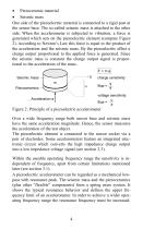
Piezoceramic material Seismic mass One side of the piezoelectric material is connected to a rigid post at the sensor base. The so-called seismic mass is attached to the other side. When the accelerometer is subjected to vibration, a force is generated which acts on the piezoelectric element (compare Figure 2). According to Newton’s Law this force is equal to the product of the acceleration and the seismic mass. By the piezoelectric effect a charge output proportional to the applied force is generated. Since the seismic mass is constant the charge output signal is proportional to the acceleration...
Open the catalog to page 9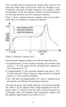
This is usually done by reducing the seismic mass. However, the lower the seismic mass, the lower the sensitivity. Therefore, an accelerometer with high resonance frequency, for example a shock accelerometer, will be less sensitive whereas a seismic accelerometer with high sensitivity has a low resonance frequency. Figure 3 shows a typical frequency response curve of an accelerometer when it is excited by a constant acceleration. 1.30 lower frequency limit calibration frequency resonance frequency Figure 3: Frequency response curve Some practical frequency ranges can be derived from this curve:...
Open the catalog to page 10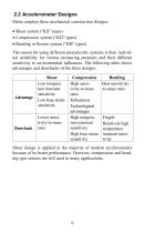
2.2 Accelerometer Designs Metra employs three mechanical construction designs: • Shear system (“KS” types) • Compression system (“KD” types) • Bending or flexure system (“KB” types) The reason for using different piezoelectric systems is their individual suitability for various measuring purposes and their different sensitivity to environmental influences. The following table shows advantages and drawbacks of the three designs: Shear design is applied in the majority of modern accelerometers because of its better performance. However, compression and bending type sensors are still used in many...
Open the catalog to page 11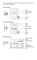
The main components of the 3 accelerometer designs are shown in the following illustrations: Shear Design: shear force Cover Seismic mass Piezo ceramics Post Socket Base Compression Design: compression force Cover Spring Seismic mass Piezo ceramics Bolt Socket Base Bending Design: bending force Friction coupling Cover Piezo ceramics Spring Seismic mass and damping piston Base
Open the catalog to page 12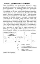
2.3 IEPE Compatible Sensor Electronics Metra manufactures many accelerometers featuring a built-in preamplifier. It transforms the high impedance charge output of the piezo-ceramics into a low impedance voltage signal which can be transmitted over longer distances. Metra uses the well-established IEPE standard for electronic accelerometers ensuring compatibility with equipment of other manufacturers. The abbreviation IEPE means “Integrated Electronics Piezo Electric”. Other proprietary names for the same principle are ICP®, CCLD, Isotron®, Deltatron®, Piezotron® etc. The built-in circuit is powered...
Open the catalog to page 13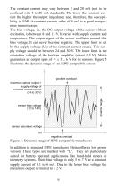
The constant current may vary between 2 and 20 mA (not to be confused with 4 to 20 mA standard!). The lower the constant current the higher the output impedance and, therefore, the susceptibility to EMI. A constant current value of 4 mA is a good compromise in most cases. The bias voltage, i.e. the DC output voltage of the sensor without excitation, is between 8 and 12 V. It varies with supply current and temperature. The output signal of the sensor oscillates around this bias voltage. It can never become negative. The upper limit is set by the supply voltage (US) of the constant current source....
Open the catalog to page 14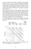
The lower frequency limit of Metra´s transducers with integrated electronics is 0.1 to 0.3 Hz for most shear and bender accelerometers and 3 Hz for compression sensors. The upper frequency limit mainly depends on the mechanical properties of the sensor. In case of longer cables, their capacitance should be considered. Typical coaxial cables supplied by Metra have a capacitance of approximately 100 pF/m. The nomogram in Figure 6 shows the maximum output span of an IEPE compatible transducer over the frequency range for different cable capacitances and supply currents. With increasing cable capacitance...
Open the catalog to page 15All Metra Mess- und Frequenztechnik in Radebeul e.K. catalogs and technical brochures
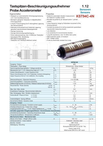
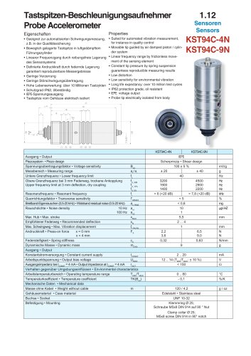
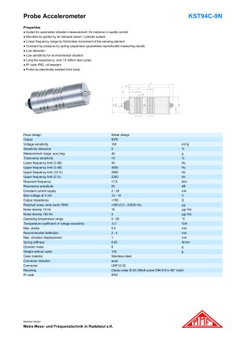 KST94C-9N
2 Pages
 Catalog 2020
2 Pages
 KS963B10
2 Pages
 KS903B10
2 Pages
 KS96B10
2 Pages
 VS11
VS112 Pages
 VS10
VS102 Pages
 Special Accelerometers
2 Pages
 Short Form Catalog
2 Pages
 Triaxial Vibration Meter
2 Pages
 Universal Vibration Meter
2 Pages
 Vibration Calibrating System
2 Pages
 IEPE100
2 Pages
 Industrial Accelerometers
2 Pages
 Miniature Accelerometers
2 Pages
 Miniature Accelerometers
2 Pages
 Shock Accelerometer
2 Pages
 Triaxial Accelerometers
2 Pages
 KB12, KB12V, KS48
2 Pages
 CB41
CB412 Pages
 Capacitive Accelerometers
2 Pages
 Accelerometer
2 Pages
 Vibration Calibrators
2 Pages
 Vibration Severity Meter
2 Pages
 IEPE Conditioning Modules
2 Pages
 Remote Charge Converters
2 Pages
 Triaxial Seat Accelerometer
2 Pages
 Triaxial Accelerometers
2 Pages
 OEM Accelerometers
2 Pages
 Low-Cost Accelerometers
2 Pages
 Miniature Accelerometers
2 Pages


Archived catalogs
 Probe Accelerometer_2010
2 Pages
 Probe Accelerometer_2018
2 Pages
 Probe Accelerometer_2008
2 Pages
 Main catalog
90 Pages
- Force sensor
- Measuring device
- Analysis software solution
- Tension/compression force transducer
- Windows software
- Calibration system
- Monitoring software solution
- 3D software solution
- Interface software
- Portable calibrator
- Single-axis accelerometer
- IEPE accelerometer
- Industrial measuring module
- Triaxial acceleration sensor
- Real-time monitoring module
- Precision calibration equipment
- Measurement monitoring module
- Compact accelerometer