- Catalogs
- Merkes GmbH - Small Motors
- New Edition Series MN
New Edition Series MN
1 /28Pages

New Edition Series MN
1 /28Pages
Catalog excerpts

Technical manual, mounting and first installation Synchronous Servomotors New Edition Series MN © Merkes GmbH Version I/12 1
Open the catalog to page 1
Technical manual, mounting and first installation 2 Ausgabe I/12 © Merkes GmbH
Open the catalog to page 2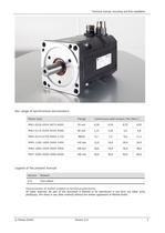
Technical manual, mounting and first installation Our range of synchronous servomotors Motor type Flange Continuous stall torque ( Mo [Nm] ) MN2-0028-0054-0075-0095 55 mm 0,28 0,54 0,75 0,95 MN3-0115-0205-0350-0480 86 mm 1,15 2,05 3,5 4,8 MN4-0510-0750-0960-1130 98mm 5,1 7,5 9,6 11,3 MN5-1200-1600-2000-2400 142 mm 12,0 16,0 20,0 24,0 MN6-1800-2400-3000-3800 190 mm 18,0 24,0 30,0 38,0 MN7-3000-4000-5000-6000 190 mm 30,0 40,0 50,0 60,0 Legend of the present manual Version Reason I/12 First edition Improvement of motors subject to technical alterations. All rights reserved. No part of this document...
Open the catalog to page 3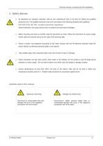
Technical manual, mounting and first installation 2. Safety Advices All operations on transport, assembly, start-up and maintenance have to be done by skilled and qualified personnel only. The qualified personnel must know and observe the following standards and guidelines: DIN VDE 0105, IEC 364, accident prevention regulations Deviant behaviour may cause serious injury to persons and may lead to damages. Before mounting and start-up carefully read the documents on hand. Follow the instructions for power supply (motor label and manual) and go by the rules of the technical data. Ensure a proper,...
Open the catalog to page 5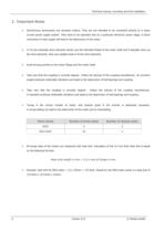
Technical manual, mounting and first installation 3. Important Notes Synchronous servomotors are precision motors. They are not intended to be connected directly to a rotary current power supply system. They have to be operated only by a particular electronic power stage. A direct connection to main supply will lead to the destruction of the motor. To fit zero backlash drive elements strictly use the intended thread at the motor shaft and if possible warm up the drive elements. Only use suitable tools to fit the drive elements. Avoid strong punches to the motor flange and the motor shaft. Take...
Open the catalog to page 6
Technical manual, mounting and first installation 4. In General 4.1. About this manual This manual describes the synchronous servomotors of the MN range and it is directed towards specialized staff having knowledge of electrical and mechanical engineering. The servomotors are operated together with the corresponding servo drives. Therefore absolutely follow the documentation of the servo drive too. If not stated in other unit all dimension to be understood in millimetre (mm). 4.2. Provisionary use Synchronous-servomotors are specially designed to run machines with high requirements to dynamics....
Open the catalog to page 7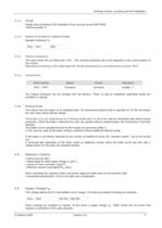
Technical manual, mounting and first installation 4.3.2. Flange Flange sizes according to IEC-standards, fit j6, accuracy as per DIN 42955 Tolerance grade: R 4.3.3. Degree of protection (without oil seal) Standard protection is: MN2 - MN7 4.3.4. IP65 Thermo protection The motor series MN are fitted with a PTC . The overload protection has to be integrated in the control system of the inverter. Operated according to the rated data the flange temperature is not allowed to exceed 65°C. 4.3.5. Connections Motor series Signal Power Standard MN2 – MN7 Connector Connector straight, 1" The mating connectors...
Open the catalog to page 9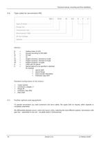
Technical manual, mounting and first installation 4.6. Type codes for servomotors MN Options: B P W U S1 S2 S4 K X = = = = = = = = = Holding brake 24 VDC Keyway according to DIN 6885 Oil seal UL Angled connector, directed to A-side Angled connector, directed to B-side Angled connector, turnable Cable with PG glands Special options to be specified in plaintext for example special shaft special flange exact encoder description Protection class IP67 Standard configuration of the motors: 4.7. 2-pole resolver Connectors, straight, 1" Flange B5 Protection class IP65 Plain shaft Further options and...
Open the catalog to page 10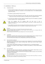
Technical manual, mounting and first installation 5. Installation / Start-up 5.1. Important notes Check the assignment between inverter and motor. Compare rated voltage and rated current of the devices. The wiring has to be carried out in accordance to the circuit diagram shown in the installation/operation manual of the inverter. Pay attention to proper grounding of inverter and motor. Place power and signal cables separately from each other. When using motor power cables with integrated brake wires, the brake wires should be shielded. The shielding braid has to be applied both-sided. Lay all...
Open the catalog to page 11
Technical manual, mounting and first installation 5.5. Power connections The power connections have to be carried out by skilled electricians only. Before starting work make sure that the systems actually is and remains without current during the installation time. Follow the safety rules according to DIN VDE 0105. The cross-sectional area of the cable has to be layed out in accordance to the rated power of the motor. The environmental conditions, the way of laying and the local legal requirements have to be taken into consideration. Strictly follow the advices of the inverter manufacturer to...
Open the catalog to page 12
Technical manual, mounting and first installation 6. Terminal Assignment 6.1. Motor MN – with resolver Resolver connector Power connector = = Intercontec Series 623, 1", 12 poles Intercontec Series 923, 1", 4 + 4 poles Power Connector Resolver Connector Pin Description = = = = = = = = Phase U Phase V Phase W Earth / SL Brake + Brake nc / Reserve nc / Reserve 1 4 3 2 C D A B 6.2. Pin 3 7 4 8 5 9 2 6 Description = = = = = = = = Cos + (S4) Cos (S2) Sin + (S1) Sin (S3) Ref + (R2) Ref (R1) Therm / PTC + Therm / PTC - Motor MN - with SinCos Encoder with Hiperface Interface Encoder connector Power connector...
Open the catalog to page 13
Technical manual, mounting and first installation MN6-1800 -1 MN6-2400 MN6-3000 MN6-3800 560 V. Winding Datas 560 V. 560 V. 560 V. Rated Speed nn min 3000 3000 3000 3000 DC Bus Voltage Udc V 560 560 560 560 Nominal AC Voltage Un V 400 400 400 400 Rated Torque Mn Nm 13,0 17,0 21,0 25,0 Rated AC Current In A 11,0 13,8 16,2 19,7 Stall Torque Mo Nm 18,0 24,0 30,0 38,0 Stall AC Current Io A 12,2 15,3 17,8 23,9 Peak Torque Mmax Nm 51 72 90 114 Peak Current Imax 45,4 60 64 93 Max. Speed nmax min-1 6000 6000 6000 6000 EMF Constant KE V/1000 89 95 102 96 Torque Constant Therminal Resistance Ph-Ph Therminal...
Open the catalog to page 23All Merkes GmbH - Small Motors catalogs and technical brochures
 Series MN
8 Pages
 Series MTK
1 Page
 Series MH
1 Page
 Series MT
1 Page
 Complete Edition Series MPM
22 Pages
 Broschure Norm-Motors IE4
4 Pages


- Electromotor
- Synchronous motor
- Alternating current motor
- Multipole motor
- Three-phase motor
- High-efficiency electromotor
- IP55 motor
- Permanent magnet motor
- Pump motor
- AC servo-motor
- 6-pole motor
- Multipole servomotor
- IP65 servomotor
- DC servo-motor
- Ultra-compact servomotor
- BLDC servomotor
- IE3 motor
- IEC motor
- Blower motor