Group: Ammega Group

Catalog excerpts

RUBBER OPEN ENDED EN TECHNICAL HANDBOOK
Open the catalog to page 1
INDEX Introduction to rubber open-ended belts Technical calculation Calculation example Calculation parameters Belt installation and feasibility table Belt failures Special execution feasibility Clamping plates Useful formulas and conversion table Data sheet RUBBER OPEN-ENDED megadynegroup.com
Open the catalog to page 2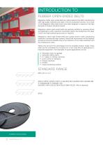
INTRODUCTION TO RUBBER OPEN-ENDED BELTS Megadyne rubber open-ended belts are rubber based timing belts manufactured with high quality materials and state of the art production process. As a result of this Megadyne offers belts which have been designed to respond to the high demands of today’s industrial market. Megadyne rubber open-ended belts are specially suitable for reversing drives and applications when rotational movements need to be transformed into linear motion and high positioning accuracy is required. Megadyne rubber open-ended belts are a great solution when substituting...
Open the catalog to page 3
CLASSIFICATIONS CLASSIFICATIONS Megadyne rubber open-ended belts are manufactured in rubber compound. They come from sleeves for spiral cut belts and from press for straight cut belts. The belt is made by: 1. BELT BACK The back side cushion protects the tensile member and permits the use of backside idlers thanks to its elasticity. 2. TENSION MEMBERS Fiberglass, steel or carbon cords of the latest technology grant the longitudinal rigidity and resistance of the belt. 3. BELT BODY The belt body is made of special polychloroprene-based, nitrile-based, HNBR or EPDM rubber compound. These...
Open the catalog to page 4
CLASSIFICATIONS BODY Megadyne rubber open-ended belts are manufactured with polychloroprene compound. Special compounds (different hardness, special properties) are available on request. See below for compound characteristics: RESISTANCE TO STANDARD BELT RESISTANCE Mineral oils Acids / Alkalis Environment agents IDENTIFICATION CODE Using the information in the table below, it is possible to identify the correct belt for every application. The code is composed of letters and numbers as the following example: 1 1. This code composed by letters and numbers indicates the selection of tooth...
Open the catalog to page 5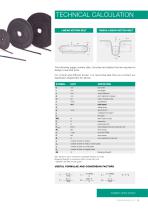
TECHNICAL CALCULATION OMEGA LINEAR MOTION BELT LINEAR MOTION BELT The following pages contain data, formulae and tables that are required to design a new belt drive. For critical and difficult drives, it is recommended that you contact our Application Department for advice. SYMBOL belt width belt length centre distance pitch diameter of pulley i total conveyed mass belt speed safety factor belt pitch peripheral force transmittable force per tooth per unit drive torque drive power force exerted by mass (m) number of teeth on pulley i number of teeth in mesh on driver pulley number of teeth...
Open the catalog to page 6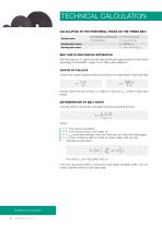
TECHNICAL CALCULATION CALCULATION OF THE PERIPHERAL FORCE ON THE TIMING BELT For horizontal & conveying drives Knowing drive torque Knowing drive power Knowing mass BELT WIDTH AND PROFILE ESTIMATION With the result of F u select the belt type profile and approximate the belt width according to DIAGRAM 1 page 10 on “Belt width selection”. CHOICE OF PULLEYS Choose the closest standard pulley according to the data sheet of each belt type z= Always verify that the chosen z is higher or equal to z min written in belt data pages. DETERMINATION OF BELT WIDTH The belt width b should be calculated...
Open the catalog to page 7
TECHNICAL CALCULATION PRE-TENSIONING The suggested installation tension is F p= F u • 2 MESHING CHECK In order to guarantee the correct function of the drive check the safety factor against break as per below: where: • BS is the Breaking Strength (see tables on belt data pages) • F u from above calculation • F p is the tension, from above calculation The σ BS outcoming value has to be higher than 11 for fiberglass and 8 for steel cords. If it is lower, please retry with the next wider belts till you will get a value higher than 11 or 8. ELONGATION You can find belt elongation from Belt...
Open the catalog to page 8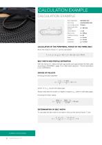
CALCULATION EXAMPLE CALCULATION EXAMPLE Automatic door Hours of daily service Desired pulley pitch diameter Centre distance CALCULATION OF THE PERIPHERAL FORCE ON THE TIMING BELT Since the mass is known, F u can be calculated: Fu = m • a + m • g • μ = 100 • 1,5 + 100 • 9,8 • 0,3 = 444 N BELT WIDTH AND PROFILE ESTIMATION With the result of F u select the belt type profile and approximate the belt width according to DIAGRAM 1 page 10 on “Belt width selection”. The first estimation is for a RPP5M15. CHOICE OF PULLEYS Knowing the pitch diameter where 14 is z min as per belt data page. Always...
Open the catalog to page 9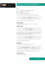
CALCULATION EXAMPLE where: • F1, from table page 10, according to input data z 24 = 12 • F2 = 1 because zm = 1 = 2 2 • F3 = 0 because n 2 / n 1 = 1 • F4 = 0 because no reverse bending Then, the belt width b should be calculated using the following formula We will choose the next higher available width: 20 > 18,7 PRE-TENSIONING The suggested installation tension is F p = 2 F u = 2 • 444 = 888 N MESHING CHECK σ BS = This value is lower than 11, that is the required minimum. Because of this you should check with the next wider available belt, that is 25 mm. This is the correct width as...
Open the catalog to page 10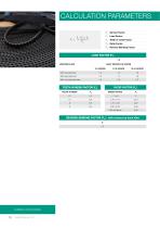
CALCULATION PARAMETERS Fs: Service Factor F2: Teeth in mesh Factor F3: Ratio Factor F4: Reverse Bending Factor LOAD FACTOR (F1) 1,0 UNIFORM LOAD DAILY SERVICE IN HOURS 3-8 HOURS With low peak load With high peak load With very high peak load TEETH IN MESH FACTOR (F2) SPEED RATIOS REVERSE BENDING FACTOR (F4) - with reverse by back idler F4 0,2 RUBBER OPEN-ENDED
Open the catalog to page 11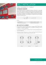
BELT INSTALLATION AND FEASIBILITY TABLE PROCEDURE TO MEASURE The preferred procedure to measure the tension of the belt is to use a Belt Tension Meter. This device consists of a small sensing head which is held across the belt to be measured. The belt is then tapped to induce the belt to vibrate at its natural frequency. The vibrations are detected by the sensing head and the frequency of vibration is the displayed on the measuring unit. The relation between belt static tension (T s) and frequency of vibration (f) may be calculated using the following formula: where: TS = static tension (N)...
Open the catalog to page 12All MEGADYNE catalogs and technical brochures
-
 Fitness industry brochure
12 Pages
-
 Packaging industry brochure
12 Pages
-
 Wood industry brochure
12 Pages
-
 QST system product brochure
8 Pages
-
 Megapaint product brochure
4 Pages
-
 PV-belts technical handbook
46 Pages
-
 MEGAPOWER technical handbook
46 Pages
-
 MEGAFLAT technical handbook
14 Pages
-
 MEGAFLEX technical handbook
58 Pages
-
 MEGALINEAR technical handbook
146 Pages
-
 Megaweld technical handbook
14 Pages
-
 V-belts technical handbook
130 Pages
-
 Engineered and speciality belt
58 Pages
-
 MegAC4T
2 Pages
-
 ACCULINK
4 Pages
-
 MEGADYNE PRODUCTS GUIDE
86 Pages
-
 MEGALINEAR XHP2
2 Pages


Archived catalogs
-
 MEGALINEAR RPP14 XHP2
2 Pages