Group: Ammega Group

Catalog excerpts

Discover Your Local Contacts The local partner of choice for sustainable power transmission belting solutions around the globe. General contact information: Megadyne Via Trieste, 16 Via S. Lucia 114 - 10075 Mathi (Torino) Italy Scan the QR code and find your local contact This information is subject to alteration due to continuous development. Megadyne will not be held liable for the incorrect use of the above stated information. This information replaces previous information. All activities performed and services rendered by Megadyne are subject to general terms and conditions of sale and delivery, as applied by its operating companies. TECHNICAL HANDBOOK
Open the catalog to page 1
INDEX Introduction to Megadyne MEGASYNC™ belts Technical calculation Calculation example Forces on shaft and bearings Causes of belt failure Center distance tables Belt data Megadyne MEGASYNC™ Imperial Megadyne MEGASYNC™ Titanium Special execution feasibility Useful formulas and conversion table Data sheet MEGASYNCTM megady
Open the catalog to page 2
INTRODUCTION TO MEGADYNE MEGASYNC™ BELTS In order to improve and make the designers’ job easier, Megadyne has decided to simplify and reorganize most of the rubber endless timing belts in just one calculation handbook. INTRODUCING THE COMPLETE MEGADYNE MEGASYNC™ FAMILY OF BELTS. In the following pages you will find all the needed information regarding technical calculation, sizes and data about Megadyne MEGASYNC™ Imperial, STD and HTB, Silver, Gold and Titanium. Our wide range of products with different power ratings and several structures allows Megadyne to always find the best solution...
Open the catalog to page 3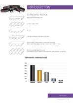
INTRODUCTION STANDARD RANGE MXL • XL • L • H • XH • XXH PERFORMANCE COMPARISON INDEX
Open the catalog to page 4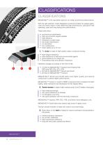
CLASSIFICATIONS CLASSIFICATIONS MEGASYNC™ is the new family name for our rubber synchronous belt products. With the right selection of belt, Megadyne synchronous belts can replace gears, chain and other styles of belt delivering high performance, lubrication-free operating, quiet and long-lasting drive performance. These belts allow: • • • • • • • • synchronous transmission high and constant angular speeds high efficiency resistance to peak loads low-noise transmission no lubrication low maintenance linear speed up to 30 m/s 1. The body is made of high-quality rubber compound having: • • •...
Open the catalog to page 5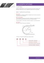
CLASSIFICATIONS COATING Megadyne MEGASYNC™ can be manufactured with special coating on the back side. Please check with our Application Department for more details. BELT SPECIFICATION BELT PITCH: the distance P in millimeters between two adjacent tooth Centres as measured along the pitch line of the belt. BELT PITCH LENGTH: the total length (circumference) of the belt in millimeters as measured along the pitch line (the theoretical pitch line lies within the tensile member). The pitch length is a value used to identify the length of a synchronous belt. BELT WIDTH: the width of the belt...
Open the catalog to page 6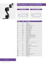
TECHNICAL CALCULATION DRIVE CALCULATION PROCEDURE CONVEYOR BELTS POWER TRANSMISSION belt width belt length actual selected length centre distance centre distance measured in teeth diameter of DriveR pulley diameter of DriveN pulley diameter of Smaller pulley diameter of Larger pulley teeth of DriveR pulley teeth of DriveN pulley teeth of Smaller pulley teeth of Larger pulley number of belt teeth number of teeth in mesh revolution/min [RPM] of the DriveR pulley revolution/min [RPM] of the DriveN pulley revolution/min [RPM] of the Smaller pulley revolution/min [RPM] of the Larger pulley total...
Open the catalog to page 7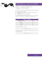
TECHNICAL CALCULATION STEP 1 - CALCULATION OF TRASMITTED POWER From Table 2 on page 7 select the appropriate service factor F S according to: • the type of the driven machine • the engine class, depending on the ratio between the peak load over the rated load • the service conditions (duty cycle category) If you are designing a drive with a speed up ratio (i = n1 / n 2 < 1) you need to consider the correction factor C m as reported in the following Table 1: TABLE 1 - CM FACTOR SPEED RATIO (I = N1 / N2) The corrected service factor CC will be: CC = FS + Cm The design power P C is obtained by...
Open the catalog to page 8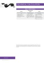
TECHNICAL CALCULATION TABLE 2 - SERVICE FACTOR FS DRIVER MACHINE CLASS A Overload peak up to 149% of the rated load Overload peak from 150% up to 249% of the rated load Overload peak from 250% up to 400% of the rated load • AC Motor: asynchronous Star-Delta starting • DC Motor: shunt wound • Internal combustion engines: 8 cyl. and up • AC Motor: asynchronous direct switch starting • Synchronous: normal torque • DC Motor: compound wound • Internal combustion engines: 6 cyl. • AC Motor: single phase;all asynchronous: double cage motors • Synchronous: high torque • DC Motor: series wound •...
Open the catalog to page 9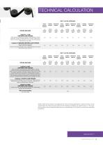
TECHNICAL CALCULATION DUTY CYCLE CATEGORY INTER- DRIVEN MACHINE Category 1: LOW UNIFORM LOAD/TORQUE Office equipment. Measuring equipment. Instrumentation. Display equipment. Laundry machinery (general). Line shaft. Agitators and mixers for liquids. Bakery machines. Conveyors: belt, light package, oven belt (ore, coal, sand). Category 2: MEDIUM UNIFORM LOAD/TORQUE Light woodworking equipment: lathes, band saws. Agitators, mixers for semi-liquid. Screens: drum, conical. Machine tools: lathes, drill presses, screw machines. DUTY CYCLE CATEGORY INTER- DRIVEN MACHINE Category 3: NOT UNIFORM...
Open the catalog to page 10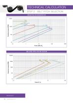
TECHNICAL CALCULATION STEP 2 - BELT PITCH SELECTION MEGADYNE AND MEGASYNC DD
Open the catalog to page 11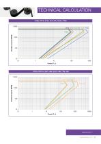
MEGASYNC™ megadynegroup.com
Open the catalog to page 12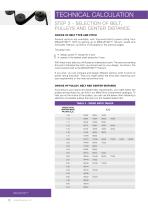
TECHNICAL CALCULATION STEP 3 - SELECTION OF BELT, PULLEYS AND CENTER DISTANCE CHOICE OF BELT TYPE AND PITCH Several options are available, with improved belt’s power rating from MEGASYNC™ RPP by getting up to MEGASYNC™ Silver3, Gold2 and eventually Titanium, as shown in the graphs in the previous pages. The graph has: • design power P c along the X-axis • speed of the fastest shaft along the Y-axis. With these input data you will locate an intersection point. The area surrounding this point indicates the pitch you should use for your design. As shown, the most powerful belt is the MEGASYNC™...
Open the catalog to page 13All MEGADYNE catalogs and technical brochures
-
 Fitness industry brochure
12 Pages
-
 Packaging industry brochure
12 Pages
-
 Wood industry brochure
12 Pages
-
 QST system product brochure
8 Pages
-
 Megapaint product brochure
4 Pages
-
 PV-belts technical handbook
46 Pages
-
 MEGAPOWER technical handbook
46 Pages
-
 MEGAFLAT technical handbook
14 Pages
-
 MEGAFLEX technical handbook
58 Pages
-
 MEGALINEAR technical handbook
146 Pages
-
 Megaweld technical handbook
14 Pages
-
 V-belts technical handbook
130 Pages
-
 Engineered and speciality belt
58 Pages
-
 MegAC4T
2 Pages
-
 ACCULINK
4 Pages
-
 MEGADYNE PRODUCTS GUIDE
86 Pages
-
 MEGALINEAR XHP2
2 Pages


Archived catalogs
-
 MEGALINEAR RPP14 XHP2
2 Pages