

PLF-SERIES

PLF-SERIES
- Constructed with high-strength anodized aluminum barrel and end caps, and a stainless steel sealing band.
- Available diameters range from 16mm to 63mm, with stroke lengths from 100mm to 5700mm, adjustable in 1mm increments.
- Operating temperature ranges from -10°C to +80°C, with a pressure range of 0.5 to 8.0 bar.
- Air connections include M5, G 1/8", G 1/4", and G3/8".
- Equal force distribution on both ends of the piston.
- Direct force transmission with torque safety.
- Available with or without magnets, offering up to 50% space savings.
- Capable of long strokes and high piston velocities, with adjustable cushioning.
- Suitable for use in explosive environments (ATEX certified).
- Maximum piston speed is 1m/s for optimal lifespan, with specific lubrication requirements for different speeds.
- Exceeding specified dynamic values can lead to damage; additional shock absorbers may be necessary.
- Deflection diagrams indicate support requirements based on load and cylinder size.
- Various mounting configurations are available, including mid-section supports and end cover brackets.
- Articulated carriers and mobile mid-section supports are provided for specific cylinder sizes.
- Force and moment tables provide maximum allowable loads and bending moments for each cylinder size.
- Detailed dimensions and mounting specifications are provided for each cylinder type.
- For piston speeds exceeding 1m/s, Viton seals are recommended.
- Switching from lubricated to non-lubricated air requires disassembly and cleaning of the cylinder.
The document lists various product codes and specifications for different types of cylinder mountings and connection sets. These include PLF series with sizes ranging from 16 to 63, and various fixation and connection sets identified by numbers such as 24/. and 25/., with specific components like brackets, screws, and anodized aluminum supports.
Details on the assembly of cylinder mountings and connection sets are provided, including the use of specific screws (10.9 zinc plated according to DIN 912) and brackets for upright positioning.
The document references DIN 912 for screw specifications, indicating adherence to standardized dimensions and materials for components.
For optimal assembly, the document suggests using the specified components and configurations, such as the use of anodized aluminum for durability and natural color for aesthetic consistency.
The document includes tables listing product codes and corresponding specifications, such as diameter sizes (Ø 16, Ø 25, Ø 32) and material types (ALU for aluminum). These tables help in identifying the correct components for specific applications.
Emphasis is placed on using the correct fixation and connection sets for different PLF sizes to ensure proper mounting and stability. The use of natural color and aluminum material is highlighted for its benefits in terms of durability and appearance.
Catalog excerpts
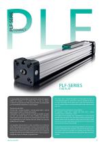
Le corps profilé est fendu dans le sens axial sur toute sa longueur. L'effort est transmis à un chariot fixé à l'axe du piston. Ce dernier est construit pour relier à travers la fente du corps profilé par l'intermédiaire d'entretoises à l'axe du piston. Transmission de l'effort : Pression d'air > Surface du piston > Axe de piston (inter) > Axe de piston (exter)> Chariot > Elément de machine. L'étanchéité à la pression d'air de la fente du profilé est réalisée avec une bande (inter) en acier, rectifiée avec précision. Cette bande d'acier est maintenue en position grâce aux deux bandes magnétiques qui sont insérées dans des rainures du corps du profilé prévues à cet effet. Une deuxième bande d'acier se situe à l'extérieur sur la fente du profilé. Elle protège de la poussière. A l'arrêt, comme pendant le déplacement, les deux bandes d'acier sont soulevées derrière le joint d'étanchéité du piston et insérées simultanément avec la rainure de guidage à l'entrée du joint d'étanchéité du piston. Avant et après le passage du chariot, les bandes se repositionnent. The entire tube is slotted throughout its full length. The force is transmitted through the load friction, which is attached to the piston axle. The design of the piston axle is that way that the inner part of the piston axle is connected through the slot with the outer part of it. Therefore the force transmission runs as follows: Air pressure > Piston area > piston axle (inner part) > piston axle (outer part) > load friction > load. The sealing of the cylinder slot is garanteed by a most precisely grinded inner steel band. The inner band is kept in position due to magnet stripes which are placed on both sides of the slot. In addition there is an outer steel band covering the slot in order to keep dust out of inner space of the cylinder. During piston movement as well as during stillstand of it both steelbands are lifted right after the piston seal and led through the piston axle by means of a separate own guiding chanel. Before and behind the piston axle both bands
Open the catalog to page 1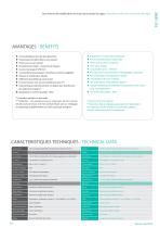
AVANTAGES / BENEFITS Forces identiques dans les deux directions Equal forces on both ends of the piston Transmission de l'effort direct, anti-rotation Piston avec ou sans aimant Force connection direct, torque safe Piston with or without magnets Encombrement réduit – économie de l'espace Course maxi jusqu'à 5700 mm 3 connections pneumatiques , amortisseurs extrêmes réglables Vitesses et accélérations élevées End caps with 3 air connections and adjustable cushioning Fast acceleration and high piston velocity Différentes possibiltés de construction Very flexible in the...
Open the catalog to page 2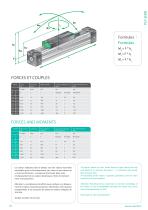
r a Formules / Formulas M = F * h a a FORCES AND MOMENTS Effect Force (N) ( ^ The figures above are max. values based on light shock free duty and speed of v< 0,2m/sec [PL-series] - v < 0,45m/sec [PLF-series]. Max. pressure 6 bar. An exceeding of the values in dynamic operations, even for short moments, has to be avoided. Attention: La combinaison des efforts peut conduire a un depassement des valeurs maximales autorisees. Afin d'eviter cette situation exceptionnelle, il est necessaire de reduire les valeurs indiquees de 10 a 20% . Veuillez consulter nos services. V) Attention: Resulting...
Open the catalog to page 4
100 Masse / Cushioning Mass Attention: Le dépassement des valeurs admissibles nécessite l'adjonction d'amortisseurs extérieurs. Pour une vitesse de piston ≥ 1m/s, le montage de joints Viton est recommandé. Pour une vitesse de piston ≤ 0,1m/s (NBR), ≤ 0,2m/s (VITON) il est nécessaire d'utiliser de la graisse N° IX, voir liste des PDR. Une vitesse de piston inférieure à 1 m/s, génère une durée de vie optimale. Pay attention to the following points: If the limits above are exceeded additional shock absorbers are necessary. For piston speeds of more than ≥ 1m/s viton seals are recommended....
Open the catalog to page 5
1L 1000 2000 3000 Flexion 1mm Deflection 1mm Distance maxi (SL) in mm - sans support intermediate N° 25 max. distance (SL) in mm - free of mounting No. 25 Diagramme-Information : ■ Le flechissement theorique calcule sans appui de 0,5 - 1mm, augmente les distances d'appui. ■ Le flechissement theorique calcule sans appui de 1 - 1,5 mm, diminue les distances d'appui. Diagram Information: ■ Calculated deflections without support of 0,5 - 1mm allow exceeding of supporting distance. ■ Calculated deflections without support of 1mm - max 1,5mm require reduction of the supporting distance.
Open the catalog to page 6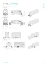
Fixation au couvercle / End cover bracket (foot) Fixation intermediate / Mid section support 25/1.0 - 2.0*
Open the catalog to page 7
Fixation intermediate mobile, Version G pour verin 025/32 Mobile Mid Section Support, Type G for Cylinder 025/32 Fixation intermediate mobile, Version W pour verin 025/32 Mobile Mid Section Support, Type W for Cylinder 025/32
Open the catalog to page 8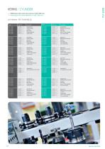
VERINS / CYLINDER • • • • Références selon choix de la course ( 0100-5700 mm ) • • • • Ident-figures for stroke definition ( 0100-5700 mm ) Standard 00: Attache rigide v=1 m/s NBR-Joints Visserie NIROSTA 3-prises d'air Standard 00: Rigid load connection v=1 m/s NBR-seals screw 10.9 zinc plated 3-air connections Speciale 01: Attache rigide v=1 m/s NBR-Joints Visserie NIROSTA 3-prises d'air Special 01: Rigid load connection v=1 m/s NBR-seals screw NIROSTA 3-air connections Speciale 02: Attache rigide v=1 m/s VITON-joints Visserie 10.9 zinguée 3-Prises d'air Special 02: Rigid load connection v=1...
Open the catalog to page 10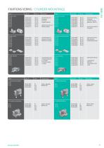
Jeu de fixation 24/.: 2 fixations 4 Vis 10.9 zinguees DIN 912 Fixation 24 pour PL 32 Position debout Connection set 24/.: 2 brackets 4 screws 10.9 zinc plated acc. DIN 912 PLF-SERIE Connection set for PL 32 upright Connection Set 25/.: body brackets anodised aluminium Jeu de fixation 225/.: 1 Attache pivotante avec douille 1 Fixation a pattes 1 Goujon Connection Set 225/.: 1 Load friction with liner 1 articulated carrier 1 bolt Couleur naturelle Matiere ALU Colour: nature Material: AL Couleur naturelle Matiere ALU Colour: nature Material: AL
Open the catalog to page 11All MEDAN catalogs and technical brochures
 New – PLS diameter 32
4 Pages
 GANTRY FOR MANIPULATOR
9 Pages
 AW-SERIE
8 Pages
 PLS - SERIES THE GLIDE
6 Pages
 PLR - SERIES
6 Pages
 PL-SERIES
11 Pages
 Linear actuator Serie MTB42
2 Pages
 Linear actuator Serie MTS55
2 Pages
 Linear actuator Serie MTS80
2 Pages
 MCQI2 series
11 Pages
 MCJI series
7 Pages
 MCMA series
13 Pages
 DUO 96 SERIES
8 Pages
 PLG - SERIES
4 Pages
 PLK - SERIES
6 Pages
 Accessories
2 Pages
 Duo96 Series
8 Pages
 Medan Catalogue 2012
70 Pages
 Pneumatic Cylinder
44 Pages


Archived catalogs
 Linear actuator Serie MTB55
2 Pages
 Linear actuator Serie MTV42
2 Pages
 Linear actuator Serie MTV55
2 Pages
 Linear actuator Serie MTV80
2 Pages

- Actuator
- Linear actuator
- Electric actuator
- Double-acting cylinder
- Pneumatic cylinder
- Single-acting cylinder
- Aluminum alloy cylinder
- Precision actuator
- Electric cylinder
- Pneumatic actuator
- Double-acting actuator
- Cylinder with piston rod
- Screw cylinder
- Belt-driven actuator
- Ball screw cylinder
- Guided actuator
- Rotary cylinder
- Guided cylinder
- Rodless actuator