MecVel - Linear Actuators Catalogue
1 /90Pages

MecVel - Linear Actuators Catalogue
1 /90Pages
Catalog excerpts

LINEAR ACTUATORS TECHNICAL CATALOGUE
Open the catalog to page 1
This page is left intentionally blank.
Open the catalog to page 2
MecVel - Edizione 2023 MecVel - Edition 2023
Open the catalog to page 4
LINEAR ACTUATORS - TECHNICAL CATALOGUE max load 1200 N max speed 90 mm/s DC motor max load 2500 N max speed 16,5 mm/s DC motor max load 2500 N max speed 110 mm/s AC/DC motor max load 4200 N max speed 30 mm/s DC motor max load 6000 N max speed 35 mm/s AC/DC motor max load 10000 N max speed 100 mm/s AC/DC motor max load 15000 N max speed 48 mm/s AC/DC motor max load 15000 N max speed 20 mm/s DC motor max load 18000 N max speed 93 mm/s AC motor max load 15000 N max speed 113 mm/s AC motor max load 25000 N max speed 55 mm/s AC motor max load 2000 N max speed 30 mm/s DC motor max load 5000 N max load...
Open the catalog to page 5
1 LINEAR ACTUATORS AND GEAR BOXES SELECTION CRITERIA GENERAL WARNING Actuators and gear boxes are devices meant to be installed into larger machines therefore they cannot be considered as safety devices (see EC law CE 89/392 and further CE 91-368,93/44,93/68). They are not elements that shall discriminate, with their use or with their fault, safeguard of people’s safety and health. Thus it is not allowed to use MecVel products as safety devices. INSTALLATION, USE, MAINTENANCE AND WASTE GUIDELINES MecVel recommendations: • • • • • A ctuators and gear boxes being installed by qualified and authorised...
Open the catalog to page 6
1 PUSH ROD Push rods can be aluminium made for actuators whose loads are low, thick chrome-plated steel for those who stand high loads or stainless steel for special applications like in food industries. ACTUATOR AND GEAR BOX APPLICATION FIELDS Actuators and gear boxes can be used in several fields and various machineries. To give an example of how different can be the applications needing actuators we can list a few like: adjusting brushes height in floor-sweeping machines, positioning blades for wood-cutting machines, textile industries, paint and chemical plants, medical equipment (different...
Open the catalog to page 7
1 POWER SUPPLY To choose a suitable actuator it is important to start finding out which kind of electric power supply is available. Not all actuators are prepared for all voltages. SELF-LOCKING There is not a sharp threshold between self locking and non-self locking conditions, because this feature is affected by gears wear, type of load, presence of vibrations, mounting position etc …When in doubt the only way of being sure of actuator behaviour is testing it on the application.When actuator is not self-locking, its positioning precision and repeatability features are lower: in this case, some...
Open the catalog to page 8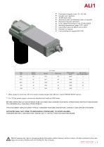
P ermanent magnet motor 12 - 24 Vdc D ouble worm gearbox A CME lead screw A luminum push rod (Stainless steel on request) P ermanent grease lubrication I P 65, tested according to rule CEI EN 60529 W orking temperature range -10°C +60°C I ntermittent duty S3 30% (5 min) a 30°C E ncoder on request Limit switches on request (ALI1-PF) Motor size * When speed is more than 30 mm/s and/or strokes longer than 200 mm, check STROKE SETUP section. ** For 12 Vdc power supply currents are doubled and loads are 20% lower. BEFORE OPERATING ACTUATOR MAKE SURE YOU READ AND UNDERSTOOD BASIC OPERATIONAL INSTRUCTIONS...
Open the catalog to page 9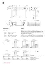
C = 40S Short Motor D = 40L Long Motor Micros are actuated by a cam lying on push-rod itself. Micro signal, for speeds higher than 30 mm/s, needs to be handled in its very impulse (I.E.when actuated) and not in its state. Alternatively, MecVel can add a bush to keep the microswitch lever pressed for a longer time avoiding switch signal mistakes, but cause loss of 10 mm of stroke. Connections C02 and C06 make a circuit which stops motor supply, so that the push rod won’t overstep the area of the two micros. This system can work only if inertia generated by the actuator and load connected to it...
Open the catalog to page 10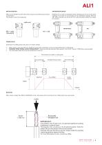
ANTIROTATION DEVICE Motor can be installed on both sides of the actuator, thus achieving two versions, as show below. The actuator is seen from backwards. Model ALI1-F can host an antirotation device, allowing push rod not to spin when travelling. Front ends A1 and A2 allow for two antirotation settings, AR0 and AR1. When using A3, A4, A5 and A7 front ends antirotation facility must always be mounted. cable exit STROKE SETUP Useful tips for handling stroke and avoid run-on-block collision • • • When stroke is more than 350 mm, add 50 mm extra-stroke as guidance, and put corresponding value in...
Open the catalog to page 11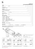
1 ORDERING KEY ALI1-F/0250/M03/24/M0/C02/P1/A2/ MODEL ALI1 ALI1-F STROKE (mm) es. 250 mm = 0250 VERSION M03 / M06 / M09 / M11 / M13 M00 = not standard speed MOTOR 12 = 12 Vdc 24 = 24 Vdc MOTOR POSITION M0 M1 MOTOR OPTIONS C01 / C08 Motor C02 / C09 2LS Diode wired C03 / C10 Motor + 2LS C04 / C11 Motor + 3LS C05 / C12 Motor + encoder C06 / C13 2LS diode wired + encoder C07 / C14 Motor + encoder + 2LS C00 Special wiring (not standard option) Note: LS (limit switches) REAR END P0 = None FRONT END A2 = Yoke A3 = Yoke + Clip A4 = Rod end A7 = M8x20 male NOTE: COMPLETE THE ORDERING...
Open the catalog to page 12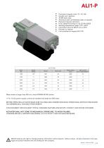
Permanent magnet motor 12 - 24 Vdc D ouble worm gearbox A CME lead screw A luminum push rod (Stainless steel on request) P ermanent grease lubrication I P 65, tested according to rule CEI EN 60529 W orking temperature range -10°C +60°C I ntermittent duty S3 30% (5 min) a 30°C E ncoder on request L imit switches on request (ALI1-PF) Motor size When stroke is longer than 200 mm, check STROKE SETUP section. ** For 12 Vdc power supply currents are doubled and loads are 20% lower. BEFORE OPERATING ACTUATOR MAKE SURE YOU READ AND UNDERSTOOD BASIC OPERATIONAL INSTRUCTIONS SHOWN ON USERMANUALS, AVAILABLE...
Open the catalog to page 13
DIMENSION Stroke < to 240 mm Stroke > to 240 mm ELECTRICAL WIRINGS Options available: Micros are actuated by a cam lying on push-rod itself. Micro signal, for high speeds needs to be handled in its very impulse (I.E.when actuated) and not in its state. Alternatively, MecVel can add a bush to keep the microswitch lever pressed for a longer time avoiding switch signal mistakes, but cause loss of 10 mm of stroke. Connections C02 and C06 make a circuit which stops motor supply, so that the push rod won’t overstep the area of the two micros. This system can work only if inertia generated by the actuator...
Open the catalog to page 14All MECVEL catalogs and technical brochures
 MecVel Blue Line
4 Pages
 HRS line
6 Pages
 AM servoactuators
6 Pages
 MecVel Silver Line
3 Pages
 MecVel Green Line
5 Pages
 MecVel - Screw Jacks Catalogue
75 Pages
 Brochure linear actuators
6 Pages
 Brochure screw jacks
6 Pages
 MecVel Red Line
3 Pages
 Safety nut
2 Pages
 Protective painting
2 Pages
 Lifta
Lifta2 Pages
 ALI3 - Special Edition
4 Pages


