TPLC005
1 /28Pages

TPLC005
1 /28Pages
Catalog excerpts
1 Introduction To grant a fast setup of the device please follow carefully the information in this manual. 1.1 Staff skill Products described in this manual are devoted to PLC programmers or automation experts only. MECT S.r.l. declines any responsibility about malfunctioning or damage caused by incorrect use of MECT devices, due to noncompliance to this manual information. MECT S.r.l has an help desk. (The products described in this manual are for personnel with experience in PLC programming, or technical specialist in the use of an electrical-driven automation. MECT S.r.l is not responsible...
Open the catalog to page 5
1.3 Terms PLC: TPLC005 Terminals: MPNC020; MPNC030 Operator panel: TP1057 System: PLC (TPLC005) with Terminals TBUS: Internal communication bus between TPLC005 and terminals. 1.4 Security Attention Switch off devices before connecting them. Attention TPLC005 must be installed in closets or cabinets accessible only by qualified personnel through a key or a tool. ESD (Electrostatic Discharge) Modules have electronic components that can be damaged by. electrostatic discharge. Be sure to be connected to ground when handle the devices. The instrument has no power switch and no internal fuse, but it...
Open the catalog to page 6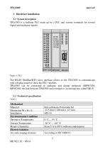
2 Hardware installation 2.1 System description TPLC005 is a realtime PLC made up by a PLC and various terminals for several digital and analogue signals. The RS485 ModBus/RTU slave interface allows to the TPLC005 to communicate with a display panel to show the PLC variables. TPLC005 can be connected to analogue and digital terminals (MPNC020; MPNC030; the link between TPLC005 and terminals is an internal bus called TBUS. 2.2 Technical specification Table 1 Mechanical Material Dimension W x H x L Installation Environmental Condition Operative Temperature Storage Temperature Relative Humidity Electric...
Open the catalog to page 7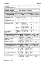
2 Pollution According to IEC 61131-2 (Degree of) Protection Degree of Protection IP 20 (Degree of Protection) Electromagnetic Compatibility Immunity to Interference for industrial areas according to EN 61000-6-2 Criterion Test Specification Values Class EN 61000-4-2 ESD EN 61000-4-3 electromagnetic fields EN 61000-4-4 burst EN 61000-4-5 surge 1 kV/2 kV (data/supply) 2/3 B Data: -/- (line/line) B 1 kV (line/earth) 2 DC 0.5 kV (line/line) 1 B 0.5 kV (line/earth) 1 supply: AC 1 kV (line/line) 2 B 2 kV (line/earth) 3 supply: EN 61000-4-6 10 V/m 80 % AM (0.15 ... 80 3 A RF disturbances MHz) Interference...
Open the catalog to page 8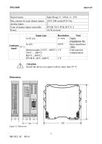
Digital inputs Max current for each digital output Analog inputs Type of analog inputs selectable Power Input type Resolution Note 0. 1mA 4÷20 mA Input impedance 9Ω 0.05V Input impedance 0÷10V Analogue N° 2 1MΩ input thermocouples J (0°C – 600°C) 1°C Cold junction T(0°C – 400°C) compensation K(0°C – 800°C) PT100 E -40°C +800°C 1°C Attention Install the device in a panel with no more than 55 °C
Open the catalog to page 9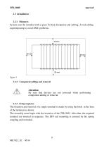
System must be installed with a space for heat dissipation and cabling. Avoid cabling superimposing to avoid EMC problems. 2.3.2 Component adding and removal Attention Be sure that devices are not powered when performing component adding or removal. The insertion and removal of a single terminal is made by using the hook at the base of the terminal as shown. The assembly must begin with the insertion of the TPLC005. After that, the required terminal are inserted in sequence. The DIN rail mounting is ensured by the spring coupling each terminal.
Open the catalog to page 10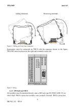
Adding terminals Removing terminals Figure 4: Adding and removing component Instruments must be connected on TBUS with the sequence shown in the figure. TPLC005 must be placed on the right and terminals on the left. All modules must be attached directly onto a DIN rail type EN 50022 (DIN 35) on which their TBUS connection modules were properly inserted. TBUS connection 9 ME7021_02 06/14
Open the catalog to page 11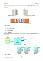
modules perform internal communication between the PLC (TPLC005) and terminals. modular connector DIN rail modular connector TBUS connection Figure 6: TBUS 3 TPLC005 wiring 3.1 Power supply 3.1.1 Isolation The system offers 3 different areas with galvanic isolation as represented in the picture below.
Open the catalog to page 12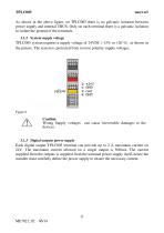
As shown in the above figure, on TPLC005 there is no galvanic isolation between power supply and internal TBUS. Only on each terminal there is a galvanic isolation to isolate the ground of the terminals. 3.1.2 System supply voltage TPLC005 system requires a supply voltage of 24VDC (-15% or +20 %) as shown in the picture. The system is protected from reverse polarity supply voltages. Caution Wrong Supply voltages can cause irreversible damages to the devices. 3.1.3 Digital outputs power supply Each digital output TPLC005 terminal can provide up to 2 A maximum current on 24V. The maximum current...
Open the catalog to page 13
The system has not internal fuses. It is recommended, for the protection of the TPLC005 input stage of the power supply, the usage of a 1A fuse, while for the power stage (terminal 2 black) 2,5A fuse. 3.1.5 Grounding The DIN rail that hosts the TPLC005 and the terminals must be thoroughly grounded in order to increase the resistance against electromagnetic interference. 3.1.6 Shielding To reduce system EMC sensitivity, the cable connecting the operator panel and TPLC005 must be a shielded cable connected to GND on both devices. 3.2 The daisy chain (DC) After power supply (system reset) the TPLC005...
Open the catalog to page 14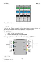
3.3 I/O wiring TPLC005 can be used stand alone, can be connected to a series of terminals of MPNC series and can be connected via ModBus to a graphical terminal. On TPLC005 there are: • 8 Input – software configurable Output • 2 software configurable universal Analogue Input In the figure below there are the terminal blocks for wiring the TPLC005.
Open the catalog to page 15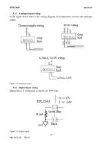
3.3.1 Analogue input wiring In the figure below there is the wiring diagram for temperature sensors and analogue inputs. Figure 12: Analogue input 3.3.2 Digital input wiring Digital lines, if configured as inputs, are PNP type. Figure 13: Digital input
Open the catalog to page 16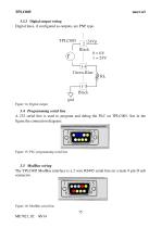
3.3.3 Digital output wiring Digital lines, if configured as outputs, are PNP type. 1-3 Black gnd Figure 14: Digital output 3.4 Programming serial line A 232 serial line is used to program and debug the PLC on TPLC005. See in the figure the connection diagram: Figure 15: PLC programming serial line 3.5 ModBus wiring The TPLC005 ModBus interface is a 2 wire RS485 serial line on a male 9 pin D sub connector. 6 Figure 16: ModBus serial line
Open the catalog to page 17All MECT SRL catalogs and technical brochures
 TPAC1008
22 Pages
 TPAC1007
14 Pages
 TPAC1006
22 Pages
 MPA-MPV M6
42 Pages
 MPA386 M6
39 Pages
 MPP P6
19 Pages
 MPA-MPV P6
18 Pages
 MP40 P6 Simple imput
16 Pages
 MP40 P6 Multi input
17 Pages
 MPX28
MPX288 Pages
 MPSN20
2 Pages
 MPCV015
20 Pages
 MPT390 M6
61 Pages
 MPT91 M1
66 Pages
 MPT90 M1
46 Pages
 MPT60 M1
45 Pages
 MPT100 M1
35 Pages
 MPCIB396 P6
41 Pages
 MPCIB20 M1
25 Pages
 MPCT301 P6
53 Pages
 MPCT300 P6
37 Pages
 MPCT30 P6
36 Pages
 MPCT20 M1
35 Pages
 MP2200 M6
44 Pages
 MP1200 P6
36 Pages
 MPPV340 M6
40 Pages
 MPO347 M6
40 Pages
 MPP323 M6
42 Pages
 MPPV010 P6
40 Pages
 MP45 P6
18 Pages
 MPM P6
34 Pages
 MP30 P2
15 Pages
 MP20 M1
35 Pages
 MPNC030
12 Pages
 MPNC020
13 Pages
 MPNC010
25 Pages
 TP1070
15 Pages
 TP1057
15 Pages
- Digital I/O
- IO module
- Digital temperature control
- Analog I/O
- Digital indicator
- Digital IO module
- LED display panel
- Panel panel meter
- Temperature controller
- Fieldbus I/O module
- Digital temperature controller
- Touch screen HMI
- Analog IO module
- Programmable display system
- Serial I/O
- PID temperature control
- DIN rail mounted I O module
- Digital counter