TPAC1006
1 /22Pages

TPAC1006
1 /22Pages
Catalog excerpts
Via Enrico Fermi, 57/59 - 10091 ALPIGNANO (TO) E-mail: srlmect® mect.it - C.F. e P.I. 04056380019
Open the catalog to page 1
1. Introduction To grant a fast setup of the device please follow carefully the information in this manual. 1.1. Staff skill Products described in this manual are devoted to PLC programmers or automation experts only. MECT S.r.l. declines any responsibility about malfunctioning or damage caused by incorrect use of MECT devices, due to noncompliance to this manual information. MECT S.r.l has an help desk. 1.2. Simbols Danger Follow this advice to avoid people injury. Warning Follow this advice to protect the device. Caution Follow this advice to have a more effective performance. ESD ( Electrostatic...
Open the catalog to page 4
Mect srl ESD (Electrostatic discharge) Modules have electronic components that can be damaged by. electrostatic discharge. Be sure to be connected to ground when handle the devices. The instrument has no power switch and no internal fuse, but it powers on immediately after connecting a correct power supply input (check the power supply value on the instrument label). Keep the power supply line as short as possible and keep it separate from other power lines. For security reasons it is necessary to have a 2 section power switch with a fuse near the instrument and easily replaceable. Avoid the...
Open the catalog to page 5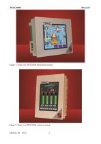
Figure 1: Front view TPAC1006 (horizontal version) Figure 2: Front view TPAC1006 (vertical version)
Open the catalog to page 6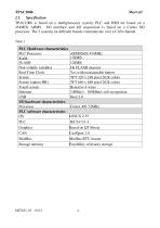
TPAC1006 Mect srl 2.1. Specification TPAC1006 is based on a multiprocessor system. PLC and HMI are based on a 454MHz ARM9, I/O interface and I/O acquisition is based on a Cortex M3 processor. The 2 systems on different boards communicate over a CAN channel. Table 1 PLC Hardware characteristics PLC Processor RAM FLASH Non volatile variables Real Time Clock Screen Screen (option HR) Touch screen Ethernet USB I/O hardware characteristics Processor PLC software characteristics OS PLC Graphics CAN ModBus Storage memory ARM926JE 454MHz 128MB 128MB On FLASH memory Yes with rechargeable battery TFT 320...
Open the catalog to page 7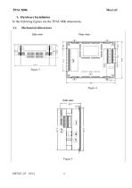
3. Hardware Installation In the following figures see the TPAC1006 dimensions. 3.1. Mechanical dimensions Side view Rear view Side view
Open the catalog to page 8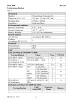
Mechanical Material Dimensions W x L x H Mounting plate 139mm x 189mm Installation Panel installation Environmental conditions Operative temperature 0 °C ... 55 °C Storage Temperature -20 °C ... +85 °C Relative Humidity 5 % a 95 % no condensation Electric isolation Air clearance According to IEC 60664-1 Pollution 2 According to IEC 61131-2 Protection Rear protection IP 20 Front protection IP65 EMC EMC according to EN 61000-6-2 (2001) Test specification Values Class EN 61000-4-2 ESD EN 61000-4-3 electromagnetic fields EN 61000-4-4 burst EN 61000-4-5 surge 1 kV/2 kV (data/supply) 2/3 Data: -/-...
Open the catalog to page 9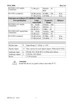
40 dB (µV/m) 47 dB (µV/m) Emissions according to EN 61000-6-3 (2001) Test specification Limit values/IQPI EN 55022 (AC supply, 66 ... 56 dB conducted) (µV) (µV) 56 dB 60 dB (µV) EN 55022 (DC supply/data, 40 ... 30 dB conducted) (µA) (µA) 30 dB EN 55022 (radiated) 30 dB (µV/m) 37 dB (µV/m) Digital input Digital output Max current for each digital output: 500mAdc@24Vdc Analogue input Analogue output Power Attention Install the device in a panel with no more than 55 °C.
Open the catalog to page 10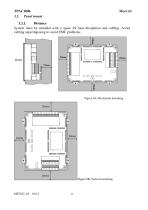
3.2.1. Distance System must be installed with a space for heat dissipation and cabling. Avoid cabling superimposing to avoid EMC problems. Figure 6A: Horizontal mounting Figure 6B: Vertical mounting
Open the catalog to page 11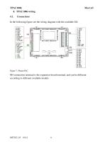
In the following figure see the wiring diagram with the available I/O. M4 connection terminal is the expansion board terminal, and can be different according to different available models.
Open the catalog to page 12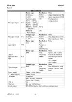
Analogue input Analogue output Digital Input/Encoder input Note Input impedance 9 Input impedance 1M Cold junction compensation Note Max Impedance: 400 Min Impedance: 1K Note Note input 2 and 3 can be used as incremental encoder input Fmax 40kHz D2: A input D3: B input Note Max 500mA for each output. 2 A max total load Resolution Max Digital output N°12 Frequency 500Hz Power supply 24Vdc 15% 400mA I/O power supply 24Vdc 15% CANOpen 1 channel Max Bit rate: 1Mbit/sec Cycle time: 10msec USB A 2.0 Ethernet Bit rate: 100Mbit/sec Serial output RS485 full duplex (by hardware configuration)
Open the catalog to page 13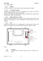
4.2.1. Isolation Device has no galvanic isolation between input, output and power supply. 4.2.2. System power supply TPAC1006 has a 24VDC (-15% +20 %) according to the scheme in the figure. System is protected against reverse power supply. As shown in the figure, the digital outputs must have a separate power supply respect the main power supply of the instrument. 4.2.3. Digital output power supply TPAC1006 digital outputs must have a separate power supply respect the main power supply of the instrument to avoid consequences on control system due to I/O problems. 4.2.4. Fuse System has no internal...
Open the catalog to page 14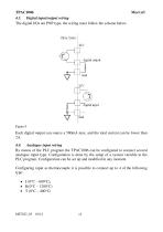
TPAC1006 4.3. Digital input/output wiring The digital I/Os are PNP type, the wiring must follow the scheme below. Each digital output can source a 500mA max, and the total current can be lower than 2A. 4.4. Analogue input wiring By means of the PLC program the TPAC1006 can be configured to connect several analogue input type. Configuration is done by the setup of a system variable in the PLC program. Configuration can be set up and modified in any moment. Configuring input as thermocouple it is possible to connect up to 4 of the following type: J (0°C – 600°C), K(0°C – 1200°C) T (0°C – 400°C)
Open the catalog to page 15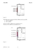
TPAC1006 can be connected to PT100. 2 different scales are possible: –40.0 °C to 200.0°C –40 °C to 800°C The scale –40.0°C to 200.0°C has a resolution of 0.1°C. The scale –40°C to 800°C has a resolution of 1°C.
Open the catalog to page 16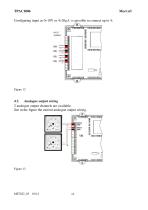
Configuring input as 0V or 4 is possible to connect up to 4: 4.5. Analogue output wiring 2 analogue output channels are available. See in the figure the current analogue output wiring.
Open the catalog to page 17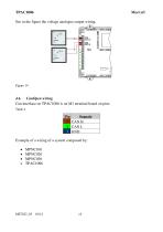
See in the figure the voltage analogue output wiring. 4.6. CanOpen wiring Can interface on TPAC1006 is on M1 terminal board on pins: Table 4 Pin Segnale 1 CAN H 2 CAN L 3 GND Example of a wiring of a system composed by: MPNC010 MPNC020 MPNC030 TPAC1006
Open the catalog to page 18All MECT SRL catalogs and technical brochures
 TPAC1008
22 Pages
 TPAC1007
14 Pages
 MPA-MPV M6
42 Pages
 MPA386 M6
39 Pages
 MPP P6
19 Pages
 MPA-MPV P6
18 Pages
 MP40 P6 Simple imput
16 Pages
 MP40 P6 Multi input
17 Pages
 MPX28
MPX288 Pages
 MPSN20
2 Pages
 MPCV015
20 Pages
 MPT390 M6
61 Pages
 MPT91 M1
66 Pages
 MPT90 M1
46 Pages
 MPT60 M1
45 Pages
 MPT100 M1
35 Pages
 MPCIB396 P6
41 Pages
 MPCIB20 M1
25 Pages
 MPCT301 P6
53 Pages
 MPCT300 P6
37 Pages
 MPCT30 P6
36 Pages
 MPCT20 M1
35 Pages
 MP2200 M6
44 Pages
 MP1200 P6
36 Pages
 MPPV340 M6
40 Pages
 MPO347 M6
40 Pages
 MPP323 M6
42 Pages
 MPPV010 P6
40 Pages
 MP45 P6
18 Pages
 MPM P6
34 Pages
 MP30 P2
15 Pages
 MP20 M1
35 Pages
 MPNC030
12 Pages
 TPLC005
28 Pages
 MPNC020
13 Pages
 MPNC010
25 Pages
 TP1070
15 Pages
 TP1057
15 Pages
- Display module
- Digital I/O
- IO module
- Digital temperature control
- Analog I/O
- Digital indicator
- Digital IO module
- LED display panel
- Panel panel meter
- Temperature controller
- Fieldbus I/O module
- Digital temperature controller
- Touch screen HMI
- Analog IO module
- Programmable display system
- Serial I/O
- PID temperature control
- DIN rail mounted I O module
- Digital counter