MPNC010
1 /25Pages

MPNC010
1 /25Pages
Catalog excerpts
USER'S MANUAL
Open the catalog to page 1
1.0 Introduction To ensure fast installation and commissioning of described devices, we recommend that you carefully read the information in this manual. 1.1 Personnel Qualification The products described in this manual are for use only by personnel with experience in PLC programming, or technical specialist in the use of an electrical-driven automation. MECT Srl is not liable for failures caused by improper usage and damage to MECT devices or other devices, due to the non-compliance to the instructions contained in this manual. MECT Srl offers technical assistance through its technical office....
Open the catalog to page 4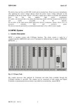
The device does not have an ON-OFF switch and an internal fuse. Power up occurs immediately after applying the correct voltage (please check the power source voltage indicated on the nameplate of the device under "Power"). Provide a supply line as direct as possible and separated from the line that supplies high power components. For safety, you must provide a two-phase disconnecting switch with fuse located near the device and easily accessible by the operator. Do not allow in the same power panel high power devices (contactors, motors, drives, ect.), or excessive moisture, heat and corrosive...
Open the catalog to page 5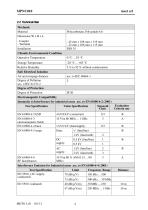
2.2 Technical Data Mechanic Material Dimension W x H x L - Coupler - Terminal Installation Climatic Environmental Condition Operative Temperature Storage Temperature Relative Humidity Safe Electrical Isolation Air and creepage distance Degree of Pollution acc. o IEC 61131-2 Degree of Protection Degree of Protection Electromagnetic Compatibility Immunity to Interference for industrial areas acc. to EN 61000-6-2 (2001) Evaluation Test Specification Value Specification Strength Criteria one Class EN 61000-4-2 ESD EN 61000-4-3 electromagnetic fields EN 61000-4-4 burst EN 61000-4-5 surge 1 kV/2 kV...
Open the catalog to page 6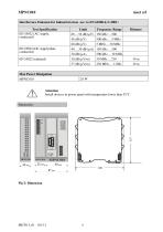
Interference Emission for Industrial areas acc. to EN 61000-6-3 (2001) Test Specification EN 55022 (AC supply, conducted) EN 55022 (DC supply/data, conducted) EN 55022 (radiated) Limit Frequency Range 66 Value/IQPI ... 56 dB (µV) 150 kHz ... 500 kHz kHz ... 5 MHz 56 dB (µV) 500 60 dB (µV) 5 MHz ... 30 MHz 40 ... 30 dB (µA) 150 kHz ... 500 kHz kHz ... 30 MHz 30 dB (µA) 500 30 dB (µV/m) 30 MHz ... 230 MHz 37 dB (µV/m) 230 MHz ... 1 GHz Attention Install devices in power panel with temperature lower than 55°C Dimension
Open the catalog to page 7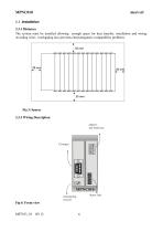
2.3 Installation 2.3.1 Distances The system must be installed allowing enough space for heat transfer, installation and wiring. Avoiding wires overlapping also prevents electromagnetic compatibility problems. Fig 3: Spaces 2.3.2 Wiring Description address and baud rate Status leds terminating resistor
Open the catalog to page 8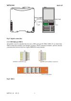
Fig 5: Signals connection 2.3.3 DIN Rail and TBUS All modules must be attached directly onto a DIN rail type EN 50022 (DIN 35) on which their TBUS connection modules were properly inserted. TBUS connection modules perform internal communication between the bus coupler MPNC010 and terminals. modular connector DIN rail modular connector TBUS connection
Open the catalog to page 9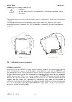
2.3.4 Component Adding and Removal Attention Be sure that devices are not powered when performing component adding or removal. The insertion and removal of a single terminal is made by using the hook at the base of the terminal as shown. The assembly must begin with the insertion of the coupler MPNC010. After that, the required terminal are inserted in sequence. The DIN rail mounting is ensured by the spring coupling each terminal. adding terminals removing terminals Fig 7: Adding and removing component 2.3.5 Daisy chain (DC) After system reset the MPNC010 coupler and the connected terminals...
Open the catalog to page 10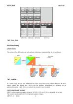
2.4 Power Supply 2.4.1 Isolation The system offers different areas with galvanic isolation as represented in the picture below. Fig 9: Isolation As shown in the picture , the MPNC010 has three areas that create isolation between the main supply voltage, the internal bus (TBUS) and the fieldbus; furthermore each terminal has an additional isolation which allows to separate the ground of each terminal. 2.4.2 System Supply Voltage MPNC system requires a supply voltage of 24VDC (-15% or +20 %) as shown in the picture. The system is protected from reverse polarity supply voltages. ME7013_01 05/ 12...
Open the catalog to page 11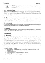
mect srl Attention Wrong Supply voltages or wrong frequency can cause irreversible damages to the devices. 2.4.3 Sensor power supply Each digital output MPNC020 terminal can provide up to 2 A maximum current on 24V. The maximum current allowed on a single output is 500mA. The current supplied from the outputs is supplied from the terminal power supply itself, hence the installer must carefully define the power supply to ensure the necessary current. 2.4.4 Fuse The system has not internal fuses. It is recommended, for the protection of the MPNC010 input stage of the supply power, the usage of...
Open the catalog to page 12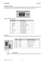
CANopen connection MPNC010 CAN interface is implemented through a D sub 9-pin male connector according to the Cia specifications. The bus is galvanically isolated from the internal bus and the IO. Fig 10: CANopen connector Pin Segnale 1 n.c Shielding connection Not connected CAN line High Not connected Not connected Status LED MPNC010 Operating status is visible through the four LED diodes placed on the top of the device. Color Green Status Description Internal bus running CANopen error Fig 11: Led Information more detailed description about Status LED meaning is provided in paragraph 3.1.4
Open the catalog to page 13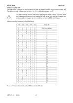
Address (module ID) The DIP switch is used to set both the baud rate and the address (module ID) of the CANopen bus. The address setting is done using switches 1 to 5, so valid addresses are 1 to 31. The address setting must be done before applying the supply voltage since one of the first transactions on power-on is reading the state of the DIP switches. Finding zero as module address triggers an error condition so the four LED start blinking. Address encoding is shown in the table below. S-1 To set a “1” move the switch on the DIP toward the ON side.
Open the catalog to page 14All MECT SRL catalogs and technical brochures
 TPAC1008
22 Pages
 TPAC1007
14 Pages
 TPAC1006
22 Pages
 MPA-MPV M6
42 Pages
 MPA386 M6
39 Pages
 MPP P6
19 Pages
 MPA-MPV P6
18 Pages
 MP40 P6 Simple imput
16 Pages
 MP40 P6 Multi input
17 Pages
 MPX28
MPX288 Pages
 MPSN20
2 Pages
 MPCV015
20 Pages
 MPT390 M6
61 Pages
 MPT91 M1
66 Pages
 MPT90 M1
46 Pages
 MPT60 M1
45 Pages
 MPT100 M1
35 Pages
 MPCIB396 P6
41 Pages
 MPCIB20 M1
25 Pages
 MPCT301 P6
53 Pages
 MPCT300 P6
37 Pages
 MPCT30 P6
36 Pages
 MPCT20 M1
35 Pages
 MP2200 M6
44 Pages
 MP1200 P6
36 Pages
 MPPV340 M6
40 Pages
 MPO347 M6
40 Pages
 MPP323 M6
42 Pages
 MPPV010 P6
40 Pages
 MP45 P6
18 Pages
 MPM P6
34 Pages
 MP30 P2
15 Pages
 MP20 M1
35 Pages
 MPNC030
12 Pages
 TPLC005
28 Pages
 MPNC020
13 Pages
 TP1070
15 Pages
 TP1057
15 Pages
- Display module
- Digital I/O
- IO module
- Digital temperature control
- Analog I/O
- Digital indicator
- Digital IO module
- LED display panel
- Panel panel meter
- Temperature controller
- Fieldbus I/O module
- Digital temperature controller
- Touch screen HMI
- Analog IO module
- Programmable display system
- Serial I/O
- PID temperature control
- DIN rail mounted I O module
- Digital counter