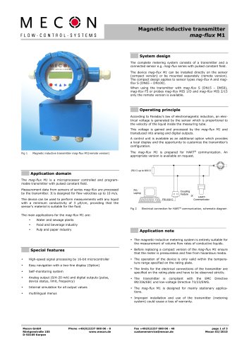
Catalog excerpts
OPERATING INSTRUCTIONS Turbo-Lux® 3 Analog Fire Pump Flowmeter System FM, LPCB and VdS approved © MECON GmbH BA / Turbo-Lux® 3 / EN / 21-08
Open the catalog to page 1
IMPRINT All rights reserved. Any reproduction or usage without written authorisation of MECON GmbH - even partial content - is strictly prohibited. Subject to change without notice. Copyright 2021 by MECON GmbH - Röntgenstr. 105 - 50169 Kerpen - Germany © MECON GmbH BA / Turbo-Lux® 3 / EN / 21-
Open the catalog to page 2
© MECON GmbH BA / Turbo-Lux® 3 / EN / 21-08
Open the catalog to page 3
SAFETY INSTRUCTIONS 1 SAFETY INSTRUCTIONS 1.1 Intended use The orifice plate flowmeter Turbo-Lux® 3 is used to measure the volume of water in closed conduits. It is suitable for any point of installation, mounting position and flow direction (in compliance of the directional arrow). The necessary approvals of the FM Approvals, LPCB and VdS Schadenverhütung GmbH are available. Warning! The operator of these measuring devices is solely responsible for the suitability, intended use and corrosion resistance of the selected materials. It must be particularly ensured that the materials selected...
Open the catalog to page 4
SAFETY INSTRUCTIONS 1.3 Safety instructions from the manufacturer The manufacturer is not liable for damages of any kind caused by the use of the device, including, but not limited to direct, indirect, incidental, punitive and consequential damages. For every product purchased from the manufacturer warranty applies, according to the relevant product documentation and the valid terms and conditions. The manufacturer reserves the right to revise the content of the documents, including this disclaimer, without notice, and is not liable in any way for possible consequences of such changes. The...
Open the catalog to page 5
DEVICE DESCRIPTION 2 DEVICE DESCRIPTION 2.1 Scope of delivery Orifice plate flowmeter Turbo-Lux® 3 Operating instructions Certificate (partially optional) Replacement gaskets (not shown here) © MECON GmbH BA / Turbo-Lux® 3 / EN / 21-08
Open the catalog to page 6
DEVICE DESCRIPTION Fig. 2 Nameplate bypass meter Turbo-Lux® 3 Description code / Order code Nominal size and process connection Pump rate (USgpm) Flow range (USgpm and lpm) Fig. 3 Nameplate orifice plate © MECON GmbH BA / Turbo-Lux® 3 / EN / 21-08
Open the catalog to page 7
INSTALLATION AND MODE OF OPERATION 3 INSTALLATION AND MODE OF OPERATION 3.1 Installation notes Information! All instruments are carefully checked for proper function before shipment. Check immediately on receipt, the outer packing carefully for damage or signs of improper handling. Report damage to the carrier and your locale sale staff. In such cases, a description of the defect, the type and the serial number of the device is indicated. Unpack the unit carefully to avoid damage. Check the completeness of the delivery against the packing list. Check the name plate, if the delivered flow...
Open the catalog to page 8
INSTALLATION AND MODE OF OPERATION » An inlet path of 5 x D requires a mounted quarter pipe before. Fig. 4 Inlet path and outflow zone at 5 x D with an one quarter pipe When using valves, fittings, ... before the orifice plate, an inlet path of min. 10 x D is always required. The outflow zone has to be min. 2 x D (fig. 5). » An inlet path of min. 10 x D is required if a valve, fitting or T-piece pipe is mounted before, where at least 5 x D must be available as a straight inlet section directly in front of the orifice plate (fig. 5). Fig. 5 Inlet path and outflow zone © MECON GmbH BA /...
Open the catalog to page 9
INSTALLATION AND MODE OF OPERATION The installation can be in any line routing - horizontal to vertical - place (fig. 6). However, it is important to ensure that the flow direction of the arrow marked on the device and corresponds to the differential pressure sampling tube (fig. 9/10, pos. 7) is in the horizontal position. For attachment of the bypass meter, sufficient clearance must be provided. Important for the compliance of the measuring tolerance is the central mounting of the pipeline. The center offset must not exceed 0.5 mm. Mounting the bypass meter The bypass meter is only...
Open the catalog to page 10
4 START-UP Read the exact value when a consistent flow has been attained and the float has reached a stable position. The pipeline must always be filled. Read the value at the greatest diameter (upper edge) of the float: Reference point For the bypass meter it is important that when starting up the pump, the shut-off-/control valve of the bypass orifice is opened min. 30 % to avoid hydraulic shocks or pressure surges that could damage the bypass meter. Fig. 8 Rotation bypass meter When the bypass meter is commissioned or set into operation, bubbles of air will initially accumulate at the...
Open the catalog to page 11
Read the exact value On the scale the flow is printed in lpm (liters per minute respectively dm³/min.), USgpm (U.S. gallons per minute) and as percentage (100 % = rated power of the pump) for each nominal size and range. The following table provides more information about the scale display. Nominal Size Pump rating (USgpm) Flow range (USgpm) Step (USgpm) Graduation Flow range (Ipm) After device usage After measurements have been taken it is recommended that the measuring tube is either drained by inverting it or removed from the flow meter body. If removed the measurement tube must be...
Open the catalog to page 12
TECHNICAL DATA 5 TECHNICAL DATA Measuring principle Input » Nominal Size » Pressure limits » Hydrostatically strength/ Pressure strength Measuring accuracy Orifice plate flowmeter with variable flowmeter as indication 2"/DN 50 grooved ends (Ø60.3 mm) 2½"/DN 65 grooved ends (Ø73.0 mm) 2½"/DN 65 grooved ends (Ø76.1 mm) 3"/DN 80 grooved ends (Ø88.9 mm) 4"/DN 100 grooved ends (Ø114.3 mm) 6"/DN 150 grooved ends (Ø165.1 mm) 6"/DN 150 grooved ends (Ø168.3 mm) 8"/DN 200 grooved ends (Ø219.1 mm) 10"/DN 250 grooved ends (Ø273.0 mm) 12"/DN 300 grooved ends (Ø323.9 mm) 500 PSI (34.5 bar) from 2" (DN...
Open the catalog to page 13
TECHNICAL DATA Fig. 9 Turbo-Lux® 3 orifice plate and bypass meter, Drawing and dimensions 2“/DN 50 - 4“/DN 100 Housing tube Bypass meter Measuring tube Float Bypass orifice Differential pressure O-Ring Screw cap Cap O-Ring Seal Filter Fig. 10 Turbo-Lux® 3 orifice plate, Drawing and dimensions 6"/DN 150 - 12"/DN 300 © MECON GmbH BA / Turbo-Lux® 3 / EN /
Open the catalog to page 14All MECON catalogs and technical brochures
-
 MENKAR KK
28 Pages
-
 MENKAR
28 Pages
-
 N4
N420 Pages
-
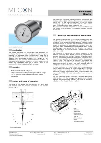 Gardex
5 Pages
-
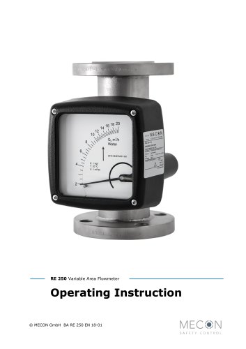 RE 250
32 Pages
-
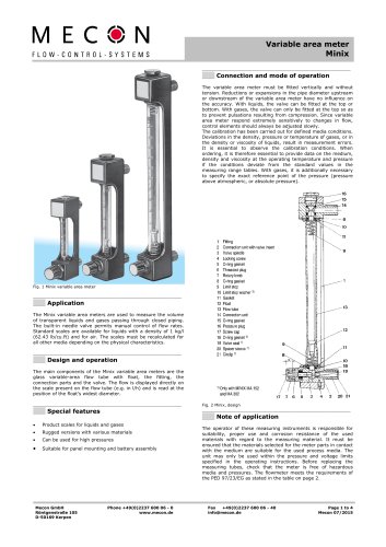 Minix
Minix4 Pages
-
 Tubux M30
20 Pages
-
 KBF
KBF20 Pages
-
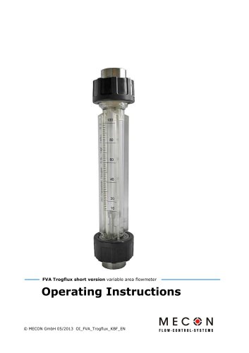
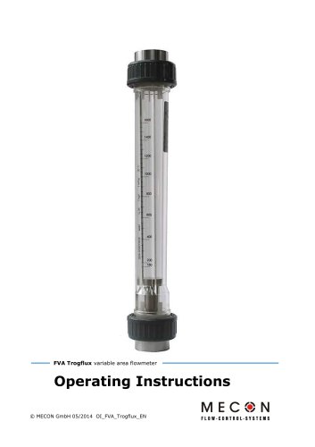 Trogflux
21 Pages
-
 mag-flux M1
35 Pages
-
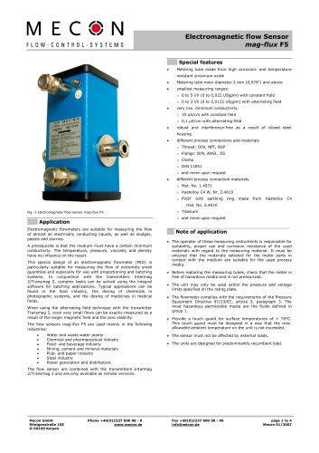 mag-flux F5
4 Pages
-
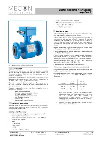 mag-flux A
9 Pages
-
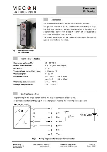 Flowmeter F I Gardex
1 Pages
-
 Product catalogue
24 Pages