Catalog excerpts
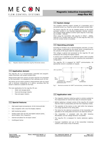
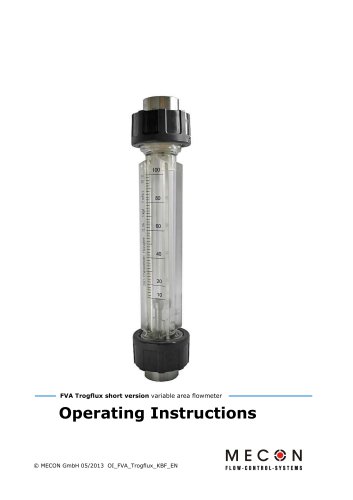
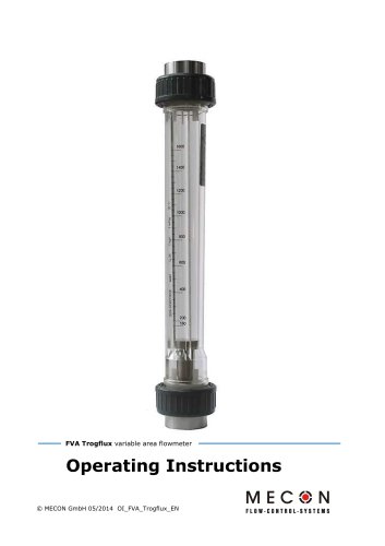
OPERATING MANUAL TUBUX M30 Float flowmeter © MECON GmbH BA / TUBUX M30 / EN / 21-03
Open the catalog to page 1
LEGAL NOTICE All rights reserved Any reproduction of this documentation, even in part and regardless of the method used, is prohibited without the prior written consent of MECON GmbH. Subject to change without notice. Copyright 2021 by MECON GmbH - Röntgenstraße 105 - 50169 Kerpen - Germany © MECON GmbH BA / TUBUX M30 / EN / 21-
Open the catalog to page 2
© MECON GmbH BA / TUBUX M30 / EN / 21-03
Open the catalog to page 3
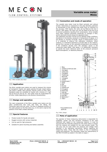
SAFETY INFORMATION 1 SAFETY INFORMATION 1.1 Intended use The TUBUX M30 float flowmeter is used to measure transparent liquid and gas flows in closed pipelines. Optionally, the device can also be used for flow monitoring if it is equipped with one or more contact switches. The device is particularly suitable for the measurement of water, transparent liquids and gas flows. The main areas of application for the TUBUX M30 are in plant and mechanical engineering, building services engineering, and water and wastewater management. Warning! Responsibility for the use of the meters with regard to...
Open the catalog to page 4
SAFETY INFORMATION By affixing the CE label, the manufacturer certifies that the TUBUX M30 complies with the legal requirements of the following EU directive, where applicable: » Pressure Equipment Directive 2014/68/EU. The most dangerous permissible media are gases and liquids in group 1. Classification as per Pressure Equipment Directive 2014/68/EU: Nominal diameter Permissible media Gases fluid group 1 and liquids fluid group 1 Gases fluid group 1 and liquids fluid group 1 Caution! For the ATEX version, the ATEX supplementary operating instructions must be observed! © MECON GmbH BA /...
Open the catalog to page 5
SAFETY INFORMATION 1.3 Manufacturer's safety information The manufacturer is not liable for any damage of any kind arising from the use of the meter, including but not limited to direct, indirect, incidental and consequential damages. Each product purchased from the manufacturer is covered by the warranty as per the relevant product documentation and the General Terms and Conditions. The manufacturer reserves the right to revise the contents of the documents, including this disclaimer, without prior notice and is not liable in any way for any consequences of such changes. Responsibility for...
Open the catalog to page 6
2 Scope of equipment 2.1 Scope of delivery » » » Flowmeter TUBUX M30 Operating manual Calibration certificate Fig. 1: TUBUX M30 with female thread, hose nozzle and flange connection The main components of TUBUX M30 flowmeters are the glass measuring cone with float, the fitting and the connecting parts. The display is on the scale on the measuring cone (e.g. in l/h). The reading edge is located at the largest diameter of the float. The device can optionally be equipped with one or more contacts for process monitoring and control. Special features: » Product scales for liquids and gases »...
Open the catalog to page 7
① Device type ② Designation code ③ Serial number ④ Maximum permissible media temperature ⑤ Maximum permissible operating pressure ⑥ Maximum permissible operating pressure at TS ⑦ Temperature range ⑧ Date of manufacture ⑨ Classification according to Pressure Equipment Directive (2014/68/EU) ⑩ User-defined device identification ⑪ CE labelling
Open the catalog to page 8
3 Installation and operation 3.1 Notes on installation Information! All devices have been carefully checked to ensure proper functioning before shipment. Carefully check the outer packaging for damage or signs of improper handling immediately after receipt. Report any damage to the carrier and to your responsible sales representative. In such cases please provide a description of the damage, the type and the serial number of the meter. Unpack the device carefully to avoid damage. Check the completeness of the delivery by referring to the packing list. Check whether the delivered flowmeter...
Open the catalog to page 9
It is important to pay attention to compliance with the calibration conditions. Information concerning the medium, the density and the viscosity at operating temperature and pressure is therefore necessary. For gases, the precise reference point of the pressure (gauge or absolute pressure) is also required. Retrofitting of contact switches is only possible if the floats with inserted magnets are used. During commissioning, the float must be guided completely past the contact for polarisation. 3.3 Mode of operation Flowmeters using the float principle operate using a vertical, conical...
Open the catalog to page 10
4 Commissioning Proper installation of the device is a prerequisite for commissioning. To avoid float bounce, start up against a closed shut-off valve, which is then slowly adjusted to the operating condition. The use of solenoid valves is especially not recommended in this context. When measuring liquids, make sure that the pipe is carefully vented to prevent pressure surges caused by gas bubbles. During the commissioning of new plants, residues may increasingly adhere to the float. In such cases, we therefore recommend cleaning the devices after a relatively short period of time. When...
Open the catalog to page 11
4.1 Contacts GSTA, GSTB and GSTW Limit switches GSTA, GSTB and GSTW are used for the remote monitoring of measured value limits. The construction consists of an M8x1 threaded sleeve and an angle coupling. A reed switch with a holding magnet is installed in the threaded sleeve. The holding magnet enables bistable switching behaviour. The limit switch is actuated by a permanent magnet built into the float. If it runs past the limit switch, the contact switches. » » » » » » NC contact, NO contact or changeover contact simple to adjust does not require a power supply long service life reliable...
Open the catalog to page 12
Fig. 4: Connection diagram GSTA Fig. 5: Connection diagram GSTB Fig. 6: Connection diagram GSTW Technical data angle connector M12 x 1 Plug connector self-assembly coupling M12 x 1 angled Metal, CuZn, Optalloy coated Contact support Grip body Protection Class IP 67 only when screwed down Outer diameter of line Core cross-section Screw-in thread Connection type Screw terminals Mechanical service life Cycles degree of contamination Rated voltage Insulation resistance Current-carrying capacity Contact resistance Ambient temperature connector © MECON GmbH BA / TUBUX M30 / EN / 21
Open the catalog to page 13All MECON catalogs and technical brochures
-
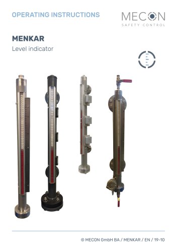 MENKAR KK
28 Pages
-
 MENKAR
28 Pages
-
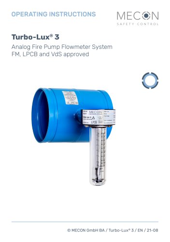 Turbo-Lux® 3
20 Pages
-
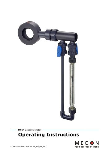 N4
N420 Pages
-
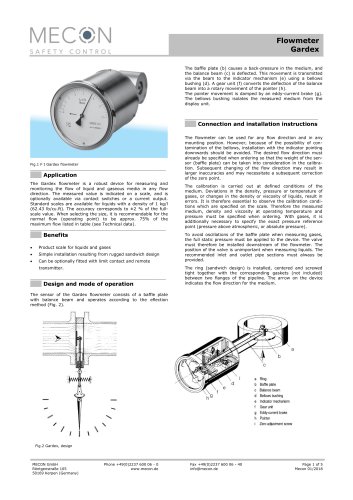 Gardex
5 Pages
-
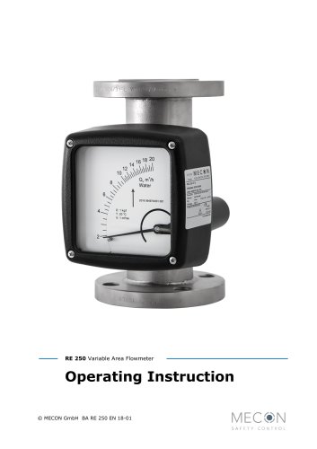 RE 250
32 Pages
-
 Minix
Minix4 Pages
-
 KBF
KBF20 Pages
-
 Trogflux
21 Pages
-
 mag-flux M1
35 Pages
-
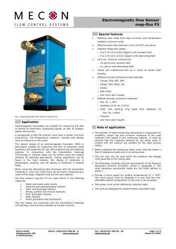 mag-flux F5
4 Pages
-
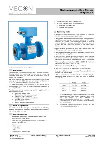 mag-flux A
9 Pages
-
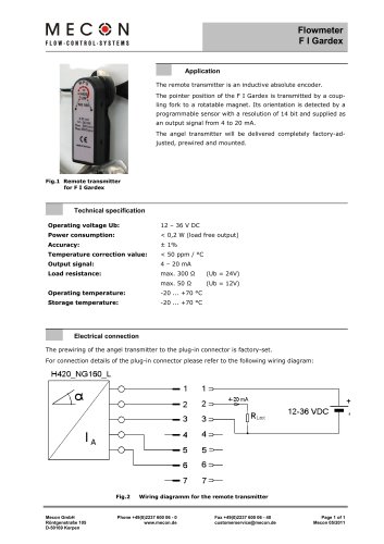 Flowmeter F I Gardex
1 Pages
-
 Product catalogue
24 Pages