Catalog excerpts

Operating Instruction RE 250 Variable Area Flowmeter
Open the catalog to page 1
All rights reserved. It is prohibited to reproduce this document, or any parts thereof, without prior written authorization of MECON GmbH. Subject to change without notice. Copyright 2018 by MECON GmbH - Röntgenstraße 105 - 50169 Kerpen - Germany
Open the catalog to page 2
1 Safety instructions _________________________________________________________ 4 1.1 Intended use _____________________________________________________________ 4 1.2 Certifications ______________________________________________________________ 5 1.3 Safety instructions from the manufacturer _______________________________________ 5 3.2 Device with electrical output (MEM) ____________________________________________ 7 3.3 Device with limit switches____________________________________________________ 7 3 Installation mode of operation _______________________________________________ 8 2.1...
Open the catalog to page 3
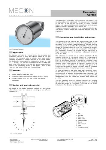
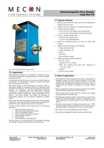
1 Safety Instructions 1.1 Intended use Safety Instructions The series RE 250 of flowmeters with a standard length of 250 mm (9.84 inch) and a completely metal design is suitable for measuring different liquids and gases in closed piping. The robust design enables the operation in rough conditions. Different types of flanges, liners and float materials meet the requirements of the pharmaceutical and chemical industries. The devices are particularly suitable for the measurement of: • • • • • • • Water Fluids Corrosion protection agents Lubricants Saturated and superheated steam Food and...
Open the catalog to page 4
Safety Instructions The manufacturer certifies for the device RE 250 meets all statutory requirements of the following EU directives by applying the CE marking: • Pressure equipment directive 2014/68/EU 1.3 Safety instructions from the manufacturer • • • • Low voltage directive 2014/35/EU * EMC-directive 2014/30/EU NAMUR recommandation NE21 * ATEX directive 2014/34/EU ** (*Devices with electrical installations) (**Devices for use in hazardous areas) The manufacturer will not be liable for any damage resulting from the use of its product, including, but not limited to direct, indirect,...
Open the catalog to page 5
When starting up the device, the following points must be observed: ● Ensure that the actual operation conditions (pressure, temperature) do not exceed the limits which are given on the nameplate of the device ● Avoid float impacts! Therefore it is recommended to start up with a closed shut-off valve to be opened slowly. The use of solenoid valves is not recommended. ● When measuring liquids, the pipes must be vented slowly to prevent shock pressure due to gas bubbles. ● When measuring gases, the pressure must be increased slowly in order to prevent high shock pressure. ● During start-up of...
Open the catalog to page 6
2.2 Device with current output (MEM) 2.3 The magneto-electrical measuring transducer (MEM) is factory-set when it is delivered to the customer. After applying the supply voltage to the device, initially the current output will be about 3.5 mA to 4 mA for a few seconds. After that a current corresponding to the pointer deflection will flow. Device with limit switches Important! Due to the influence of the float magnet, the MEM transmitter will only output the correct current if the pointer position is caused by the float. Turning the pointer manually will cause incorrect values, but it is...
Open the catalog to page 7
3 Installation and mode of operation 3.1 Notes on installation Installation Information ! All instruments are carefully checked for functional capability before shipment. Upon receipt of the device please carry out a visual inspection of the outer packing for damage or improper handling. Please contact the delivery carrier if you discover any defects. In such cases a description of the defect, the type and the serial number of the device are needed. Unpack the equipment with care to prevent damage. Information ! All instruments are carefully checked for order conformity. Please check the...
Open the catalog to page 8
ca. 200 mm at a selected distance while observing whether the position of the pointer on the display changes. ● Specify the installation zone regarding a reliable reading of the displayed values and adequate spacing for servicing. ● An inlet run upstream and an outlet run downstream the device is not necessary in case of a linear media flow profile. In cases of highly asymmetrical flow profiles, however, additional measures (e.g. inlet tracks, flow rectifiers) with a length of at least 250 mm could be appropriate to ensure the measuring accuracy. ● Avoid the installation of unilaterally...
Open the catalog to page 9
Process connection Tightening torques for devices with PTFE liner To prevent a malfunction of the flowmeter caused by ferromagnetic substances contained in the medium (such as weld beads) a magnetic filter should be mounted in flow direction upstream of the instrument. This kind of filter is also recommended if such particles cannot be avoided in standard operation. Like other devices of this series the variable area flowmeter RE 250 operates according to the The measuring unit consists of a metal tube with a measuring ring in which a float can move up and down. The media is flowing upwards...
Open the catalog to page 10
Classification in accordance with the Pressure Equipment Directive 2014/68/EU: Process connection EN1092-1 ANSI B16.5 DN 15 DN 20 DN 25 DN 32 DN 40 DN 50 DN 65 DN 80 DN 100 DN 125 DN 150 Gases Gases Gases Gases Gases Gases Gases Gases Gases Gases Gases Admissible media fluids fluids fluids fluids fluids fluids fluids fluids fluids fluids fluids ● Store the device in a dry and dust-free place. ● Keep away from direct sun and heat. ● Avoid external loads to the device. fluid fluid fluid fluid fluid fluid fluid fluid fluid fluid fluid group group group group group group group group group group...
Open the catalog to page 11
4.3 Replacing float Service Devices with measuring ring For devices with standard measuring ranges starting from 5 - 50 l/h (gases: 0.15 – 1.5 m³/h) the replacement of the float can be provided by the customer: ● Remove the device from the piping. ● Fix the device ideally in a horizontal position, ensuring that the fitting will not be damaged. upper guide bracket from torsion by fixing the using a suitable tool. ● Remove the self-locking nut lower guide bracket ● Take the float upwards out of the measuring unit. ● Insert the new float into the fitting from the top. At the same time...
Open the catalog to page 12All MECON catalogs and technical brochures
-
 MENKAR KK
28 Pages
-
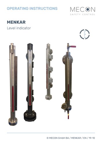
 MENKAR
28 Pages
-
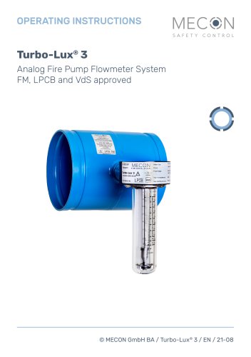 Turbo-Lux® 3
20 Pages
-
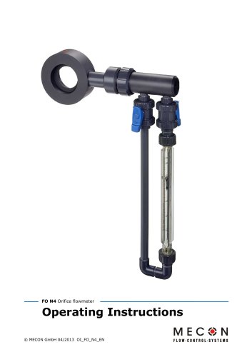 N4
N420 Pages
-
 Gardex
5 Pages
-
 Minix
Minix4 Pages
-
 Tubux M30
20 Pages
-
 KBF
KBF20 Pages
-
 Trogflux
21 Pages
-
 mag-flux M1
35 Pages
-
 mag-flux F5
4 Pages
-
 mag-flux A
9 Pages
-
 Flowmeter F I Gardex
1 Pages
-
 Product catalogue
24 Pages