Catalog excerpts
Operating Instructions © MECON GmbH 04/2013 OI_FO_N4_EN
Open the catalog to page 1
All rights reserved. It is prohibited to reproduce this document, or any parts thereof, withoutprior written authorization of MECON Flow Control Systems GmbH. Subject to change without notice. Copyright 2013 by MECON Flow Control Systems GmbH - Röntgenstraße 105 - 50169 Kerpen
Open the catalog to page 2
Safety Instructions 1 Safety Instructions 1.1 Intended use The FO N4 orifice flowmeter is used to measure the flow of transparent liquids and gases in closed pipes. The flowmeter is suitable for any mounting location, position and flow direction. The flowmeter can also be used for flow monitoring if equipped with limit contacts. Warning! The operator of these measuring devices is solely responsible for the suitability, intended use and corrosion resistance of the selected materials. It must be particularly ensured that the materials selected for the wetted parts of the flowmeter are...
Open the catalog to page 4
Safety Instructions 1.3 Safety instructions from the manufacturer Disclaimer The manufacturer will not be liable for any damage resulting from the use of its product, including, but not limited to direct, indirect , incidental, punitive and consequential damages Any product purchased from the manufacturer is warranted in accordance with the relevant product documentation and our Terms and Conditions of Sale. The manufacturer reserves the right to revise the content of its documents, including this disclaimer, without prior notifica, and will not be liable in any way for possible...
Open the catalog to page 5
2 Start-up When starting up the unit, the following points must be observed: • Make sure that the actual operating conditions (pressure and temperature) do not exceed the limits specified on the nameplate. The calibration is carried out for defined conditions. It is essential to ensure compliance with the calibration conditions. Deviations of the density, pressure or temperature of gases, as well as density and viscosity of liquids, result in errors. Bends, valves and the like must be installed in such a distance of the orifice unit that disturbances have subsided. Orifice units with large...
Open the catalog to page 6
3 Installation 3.1 Installation instructions Information ! All instruments are carefully checked for proper function before shipment. Check immediately on receipt, the outer packing carefully for damage or signs of impro handling. Report damage to the carrier and your competent sales staff. In such cases, a description of the defect, the type and the serial number of the device is indicated. Information ! Unpack the unit carefully to avoid damage. Information ! Check the completeness of the delivery by using the packing list. Check the name plate, if the delivered flow meter is according to...
Open the catalog to page 7
4 Service 4.1 Storage Keep the device in a dry and dust-free place. Keep away from direct sun and heat. Avoid external load to the device The storage temperature range for standard devices with electrical components is about -40 … +70 °C (– 40 °F … 158 °F) 4.2 Maintenance and cleaning The devices were built within scope of low maintenance but periodically the flowmeters should be inspected for signs of corrosion, mechanical wear as well as damage to the fitting and the display unit. We advice to carry out inspections at least once a year. F3,or a detailed inspection and cleaning the device...
Open the catalog to page 8
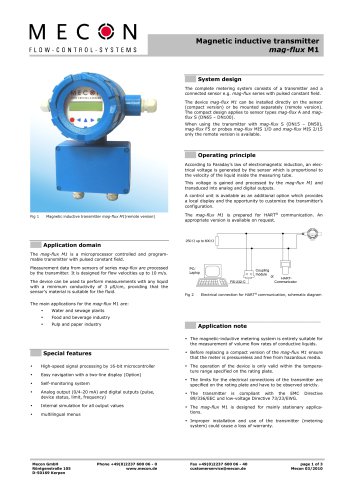
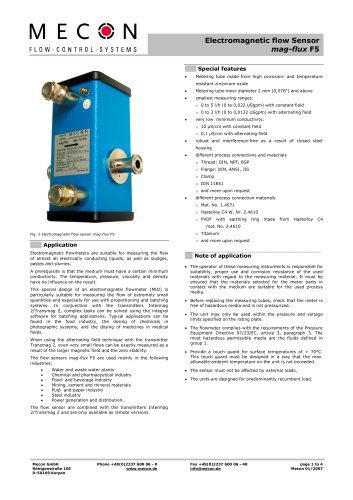
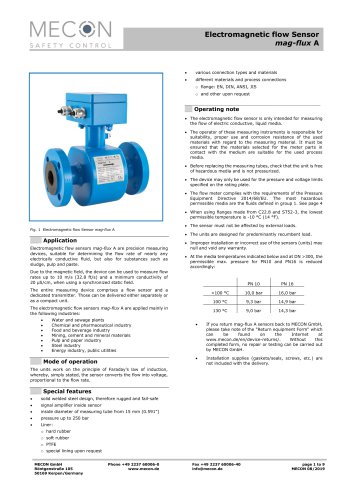
Device Description 5 Device Description 5.1 Scope of delivery Operating instructions Certificates (optional) Information ! Please check the delivery for completeness using the packing list. Fig. 2 Standard device with bypass and orrifce made of PVC The FO N4 orifice flowmeter primarly consists of an orifice plate as the sensor and a float as the display element. A differential pressure is produced across the orifice plate which is fitted in the main stream between two flanges in the piping. In a bypass, this differential pressure produces a volume flow in a variable area meter. The height...
Open the catalog to page 9
Device Description Special features: • Complies with requirements for treatment and disinfection of swimming / bathing pools (DIN 19 643) Simple installation Direct visualitzation of flow rate in bypass Suitable for any mounting positions without reduction in accuracy 5.3 Nameplate Important! Please refer to the device nameplate to ensure that the device is built according to your order. Check particularly for the corect supply voltage Code number Year / Serial number Device specific serial number and the year it was built Category acc. To Pressure Equipment directive (PED) Maximum...
Open the catalog to page 10
Description code 7 Description Code The description code consists of the following elements: Flow tube Trogamid Polysulfone 2 Nominal diameter P DN 25 (1") Q DN 32 (1 ¼") A DN 40 (1 ½" ) B DN 50 (2") C DN 65 (2 ½") D DN 80 (3") E DN 100 (4") F DN 125 (5") G DN 150 (6") H DN 200 (8") J DN 250 (10") K DN 300 (12") L DN 350 (14") M DN 400 (16") 3 Measuring ranges (for water in [m³/h] (refer to the following table)) A Standard range A B Standard range B C Standard range C D Standard range D E Standard range E Z Special range (with additional Y01) A
Open the catalog to page 11
Description code Float material Mat.No.. 1.4305 Mat.No. 1.4571 Mat. No..1.4571 with Magnet PVC weighted PVC weitghted with Magnet Connection standard DIN 2501 ASME B16.5 150 RF Contacts (only with magnetic float) without Contact K18/A (closes when limit is fallen below) Contact K18/B (closes when limits exceeded) 2 Contacts K18/A 2 Contactc K18/B 1 each Contact 18/A und K18/B 7 Bypass pipe / Orifice AW PVC / PVC PW PP / PP Bx PVC / stainless steel mat. No.1.4571 Qx PP / stainless steel mat. No. 1.4571 xP DN 25 (1") xQ DN 32 (1 ¼") xA DN 40 (1 ½") xB DN 50 (2") xC DN 65 (2 ½") xD DN 80 (3")...
Open the catalog to page 12
Measuring ranges for liquids 7 Measuring ranges for liquids Standard measuring ranges for liquids (p= 1kg/l (62,43 lb/cu.ft), viscosity 1mPa.s (1cP)) Nominal diameter overpressure ≥ 0,5bar Minimum measuring range Maximum measuring range
Open the catalog to page 13All MECON catalogs and technical brochures
-
 MENKAR KK
28 Pages
-
 MENKAR
28 Pages
-
 Turbo-Lux® 3
20 Pages
-
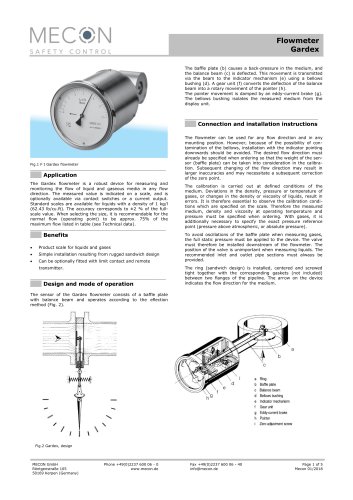 Gardex
5 Pages
-
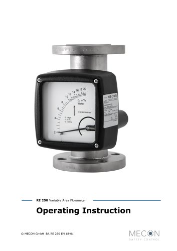 RE 250
32 Pages
-
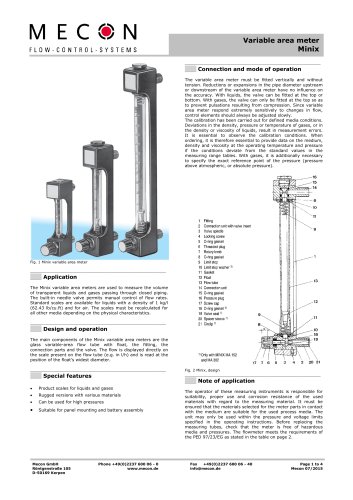 Minix
Minix4 Pages
-
 Tubux M30
20 Pages
-
 KBF
KBF20 Pages
-
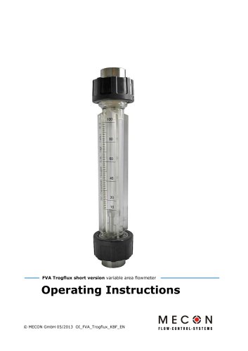
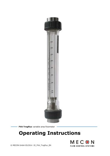 Trogflux
21 Pages
-
 mag-flux M1
35 Pages
-
 mag-flux F5
4 Pages
-
 mag-flux A
9 Pages
-
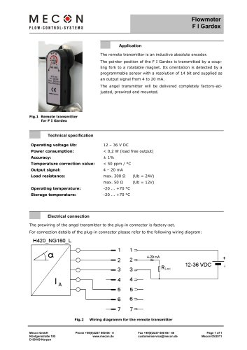 Flowmeter F I Gardex
1 Pages
-
 Product catalogue
24 Pages